NI VirtualBench Calibration Procedure | © National Instruments | 67
8. Call PS Measure Adjustment Point with the following parameters:
• Channel =
ps/+6V
• Reference Value—Supplied from the DMM measurement in step 7
9. Repeat steps 5 through 8 for each adjustment point on this channel.
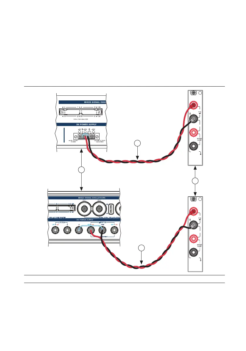
10. Disconnect all connections and connect Channel +25 V to Volts HI, and Common Floating
GND to Volts LO as shown in Figure 36. Connect GND and Common Floating GND with
a jumper.
Figure 36. Cable Connections For +25 V Voltage Programming and Measurement
Accuracy Adjustment
11. Repeat steps 4 through 9 for the ps/+25V channel.
1 VirtualBench DC Power Supply 2DMM 3 Cabling Wire
1
3
3
HI
LO
300V
MAX
AMPS
500V MAX
HI
LO
1kV
MAX
3A, 250V
MAX
INPUT
MAX
1kV
2
HI
LO
300V
MAX
AMPS
500V MAX
HI
LO
1kV
MAX
3A, 250V
MAX
INPUT
MAX
1kV
 Loading...