4.3 Removing the Current PCB
The procedures in section 4.2 must be completed before beginning these steps.
1. Positioning guides, connectors to the LED PCB, power cable from the flexible mounting
tube and cables to the ON/Standby switch hold the Current PCB.
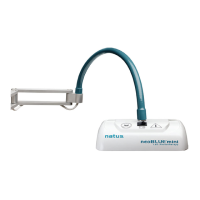
2. Remove the Current PCB by pulling it out of the light enclosure as shown in figure 4.
FIGURE 4
3.
Disconnect the power cables from the Current PCB.
Caution: Examine the wire color for reinstallation. Ground or common is closest to the
LED PCB.
4. Remove the ON/Standby switch wires by pulling them off the switch.
Note: Polarity is not important for the switch wires. However, position is important. Mark
the two appropriate switch lugs for correct reinstallation.
If you are replacing the Current PCB, obtain the replacement and reverse the previous
steps.
5. If no further repair is required, reverse all previous steps in chapter 4, return to chapter
2, and perform Safety and Performance Verification Tests. If further disassembly is
required, store the Current PCB in a safe anti-static environment and proceed to section
4.4, Removing the ON/Standby switch.
neoBLUE
®
mini System Service Manual P/N 051466F
13
 Loading...
