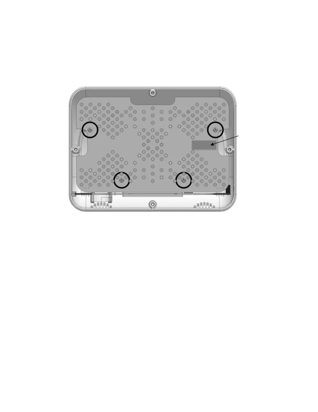
4.2 Removing the LED PCB
The procedure in section 4.1 must be completed before beginning these steps.
Remove the four Phillips head screws securing the LED PCB to the light enclosure. Locations
are circled in figure 3.
Timer
FIGURE 3
CAUTI
ON: Do not grasp the LEDs to remove the LED PCB from the light enclosure.
1. The LED PCB is connected to the Current PCB by two 4-pin connectors on the upper
corners of the LED PCB. The board is removed by pulling the LED PCB away from the
Current PCB.
Note: The Current PCB is held in the light enclosure by positioning guides, which may
also come out when the LED PCB is removed.
2. If you are replacing the LED PCB, obtain the replacement and reverse the previous
steps.
Note: When reconnecting the LED PCB, verify the JP1 and JP2 connectors are mated
correctly.
3. If no further repair is required, reverse all previous steps in chapter 4, return to chapter
2, and perform Safety and Performance Verification Tests. If further disassembly is
required store the LED Panel in a safe anti-static environment and proceed to section
4.3, Removing the Current PCB.
neoBLUE
®
mini System Service Manual P/N 051466F
12
 Loading...