NV5/NV3.5 Troubleshooting Manual Responding to alarms
Issue 3.2 2014-12-10 Page 1-41
LVPS module A (U3). Disconnect P6 from A6J7 for LVPS module B (U4). The LVPS
module’s green lamp should turn off. Verify ac power has been disconnected from the LVPS
module by using a digital voltmeter to verify 0 V between the L and ground terminals and
between the N and ground terminals.
3. Disconnect all wiring from the LVPS module’s terminal block, noting the specific destination
of each wire.
4. Using a 4 mm hex key (not provided), loosen the two M5 cap screws securing the LVPS
module to the transmitter. Remove the LVPS module and its mounting plate from the
transmitter.
5. Remove the two M4 screws that secure the LVPS module to its mounting plate.
6. Locate or obtain a replacement LVPS module (Nautel Part # UG68). Reverse Step 1 and
Step 5 to reinstall the new LVPS module. If necessary, refer to Section 4, “Wiring/connector
lists” on page 4-1 to locate wiring details.
7. From the AUI’s System Review page, select Controller and view the +5V A or +5 V B meter,
depending on which LVPS module was replaced. If necessary, adjust the potentiometer on
the rear of the LVPS module until the meter reading is 5.6 V.
8. The transmitter should resume normal operation and the alarm should clear.
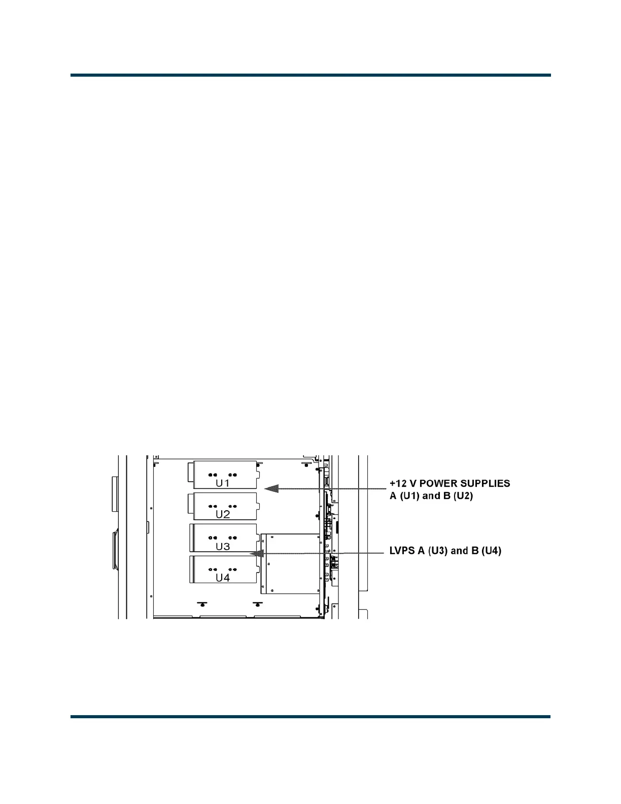
Figure 1.6: Location of +12 V and Low Voltage Power Supplies
Partial Side View - Panel Removed
Rear