19
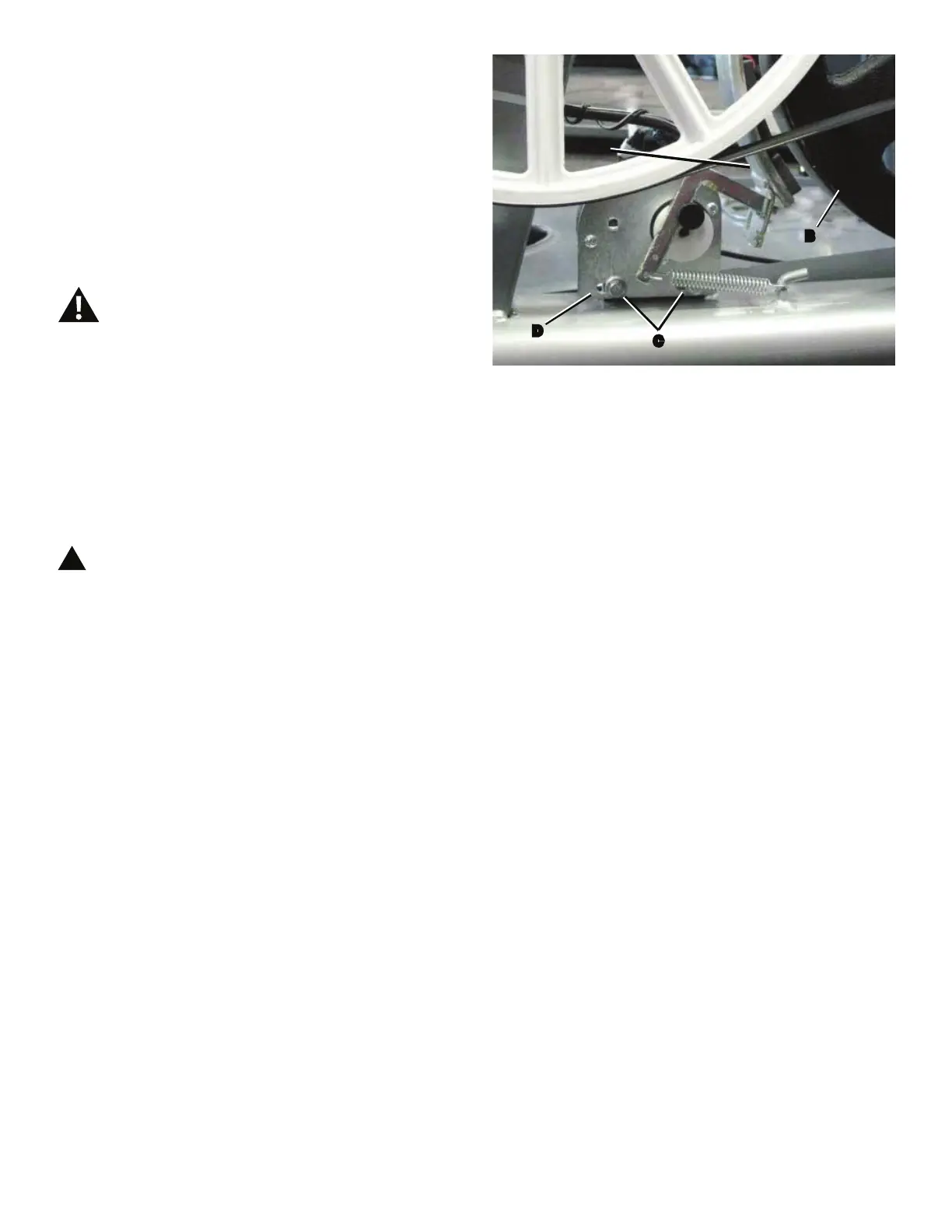
7RDGMXVWWKH%UDNHWHQVLRQORRVHQWKHKH[KHDGEROWV
(C) and move the Servo Motor assembly (D) until the closest
point on the Brake Magnet (A) is within 3.0 mm (1/8”) of the
Flywheel (B). Tighten the bolts.
Note: If the cardboard is not 3mm (1/8”) thick, you can
use the pages of a paperback book to measure
WKHJDS$SSUR[LPDWHO\SDJHVVKHHWV PP
7. Turn the power on again. Use the console to check the
resistance adjustment.
0DFKLQHLVRQ&XUUHQWLVDFWLYH7KHUHLVULVNRI
HOHFWULFDOVKRFN
Note: Before fully attaching the Shrouds, remove the
cardboard from between the Brake Magnet (A) and
the Flywheel (B). Power up the machine to verify
that the Magnet Arm can move freely, and that the
Brake Magnet and Flywheel do not touch.
8. Final Inspection
Inspect your machine to ensure that all hardware is tight and
components are properly assembled.
!
Do not use until the machine has been fully
assembled and inspected for correct performance
LQDFFRUGDQFHZLWKWKH2ZQHU¶V0DQXDO
A
B
D
C

 Loading...