31
1RWH Your machine may not match the image. For reference only.
To remove the Main Shrouds, start at Step 1. To remove only the Rear
Shrouds, go to Step 10.
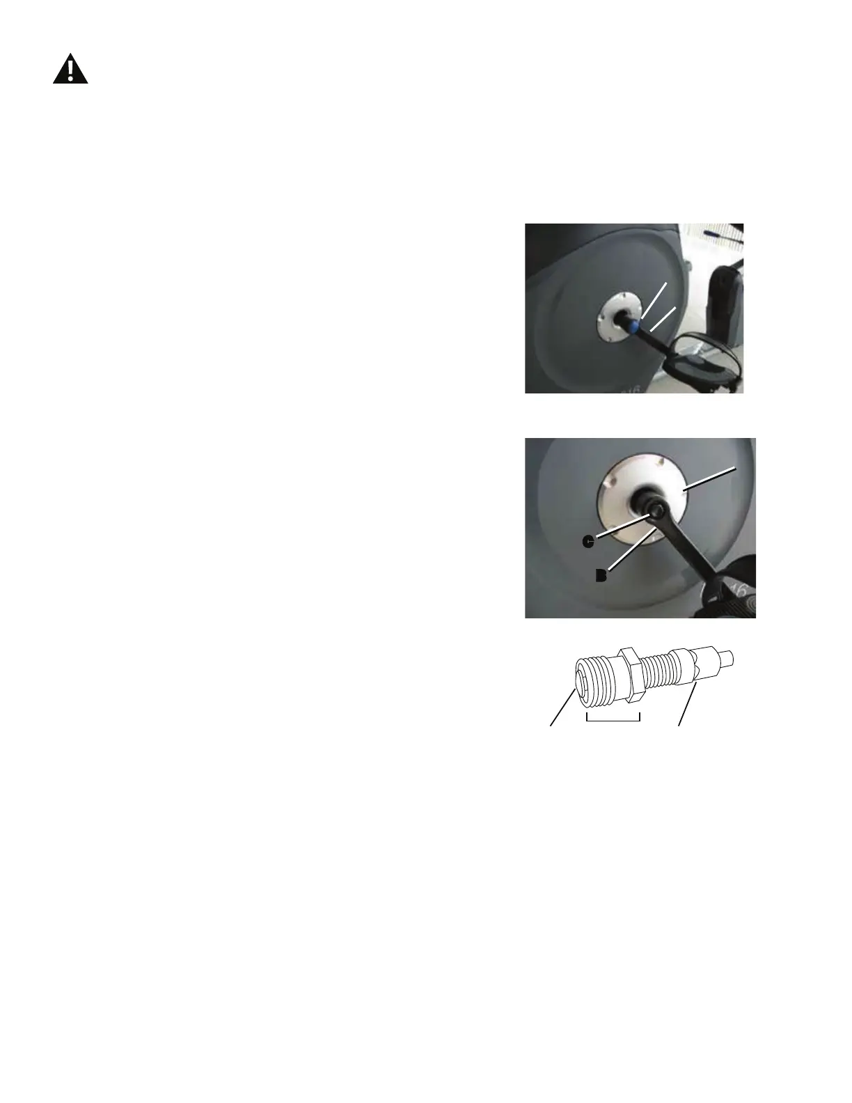
8VLQJDÀDWKHDGVFUHZGULYHUUHPRYHWKHWKUHDGHG&DS$
IURPWKH&UDQN$UP%WRH[SRVHWKH+H[+HDG%ROW&
8VLQJDZUHQFKDQGVRFNHWUHPRYHWKH+H[+HDG%ROW&
3. Thread the Crank Puller into the Crank Arm (B). When the
Crank Puller is in the correct position, only 1-2 threads on the
outer portion (CP2) of the Crank Puller should show.
Note: Be sure the end of the Bolt (CP1) of the Crank Puller is
ÀXVKZLWKWKH1XW&3DVVKRZQEHIRUHXVH
4. Using a wrench, turn the inner portion (CP3) of the Crank
3XOOHUFORFNZLVH7KH&UDQN$UP&ZLOOVOLGHRႇDVLWLV
tightened.
5. Twist the Crank Covers (P) toward the back of the machine
to disengage the inner tabs. Carefully remove the Crank Covers
and set them safely aside for reassembly.
Disconnect all power to the machine before you service it.
CP1 CP2 CP3
A
B
C
B
P
 Loading...