41
NOTICE:,WLVQHFHVVDU\WRUHPRYHWKH6KURXGVIRUWKLVSURFHGXUH5HIHUWRWKH³5HSODFHWKH6KURXGV´SURFHGXUH
1RWH<RXUPDFKLQHPD\QRWPDWFKWKHLPDJH)RUUHIHUHQFHRQO\
1. Carefully remove the Shrouds. Refer to the “Replace the
Shrouds” procedure in this manual.
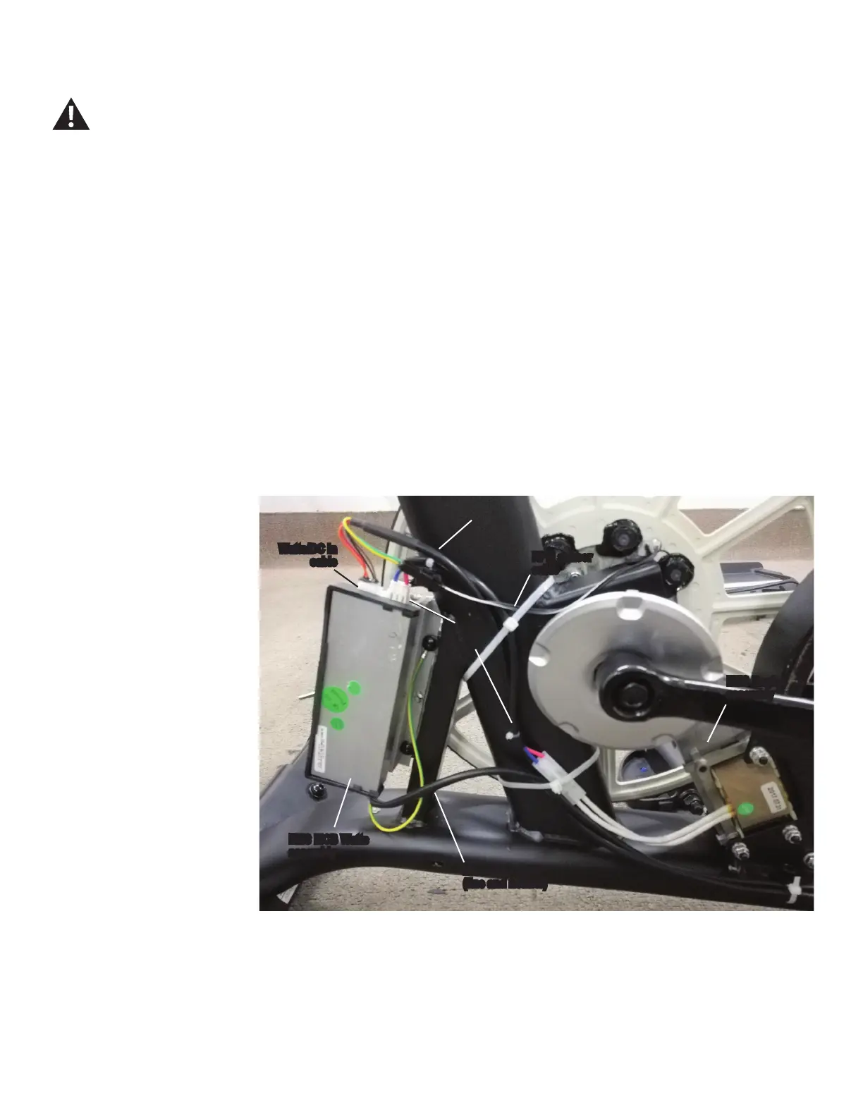
2. Observe the cable routing from the EMS Motor Control
Board (MCB) Watts assembly on your machine.
• EMS Cable (EMS MCB Watts assembly to EMS Engine
assembly)
• EMS MCB Cable (Power inlet/switch to MCB)
• Input/Output (I/O) Cable (EMS MCB Watts to Console)
- Watts/DC In Cable, Upper (EMS MCB Watts to
Console)
- RPM Sensor Cable (RPM Sensor to Console)
Note: Be sure to note where all cables are routed for re-
assembly.
3. Remove the ziptie(s) that
holds the EMS Cable.
Disconnect all power to the machine before you service it.
EMS Engine
assembly
Watts/DC In
cable
EMS MCB Watts
assembly
EMS MCB cable
(line and neutral)
EMS
cable
I/O cable
(to Console)
RPM sensor
cable
EMS MCB Watts (U628) - right side view

 Loading...