-46-
Service Manual CP-785F
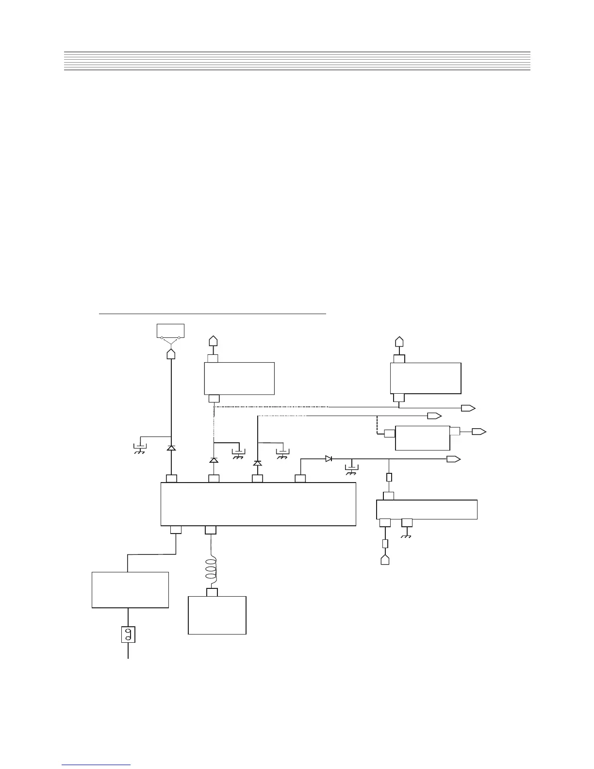
On normal run mode, I501 microcontroller pin 63 (power) is set to high
So, I810 controlled rectifier is not conducting
- Q809 is conducting. So, Q808 is not conducting and Q807 is conducting
- So, Q807 collector is connected to the ground and I810 controlled rectifier gate pin is
set to low (no conducting)
So, current from 11V DC voltage (from T801 SMPS transformer pin 13) does not flow through
Q811 and Q810 transistors but flows through I806 IC error amplifier
- Q809 is conducting. So, Q810 is not conducting and no current flows from Q810
collector to the ground
Therefore, the power supply circuit diagram is the one shown on the next paragraph
* power supply circuit diagram during TV set normal run
I820
5V
REGULATOR
I823
3.3V
REGULATOR
I602
316
TDA894X
5V
3.3V
3
3
1
1
11V
8V
6V
1
3
143V (CP785)
D820
D860
D830
D831
C832
C823
C861
12
14
15
18
2
4
C813
R823
R810
11V
2
3
I806
IC ERROR AMPLIFIER
12V
8V
12V
143V
T801 SM PS TRANSFORM E R
D801... D804
(GRAETZ BRIDGE)
D
I801
MO SFET AND
CONTROL IC
SW 801
POW ER
SW ITCH
MAIN AC VOLTAGE
L801
Ι822
8
V
REGULATOR
1
3
Power supply operation during TV set normal run