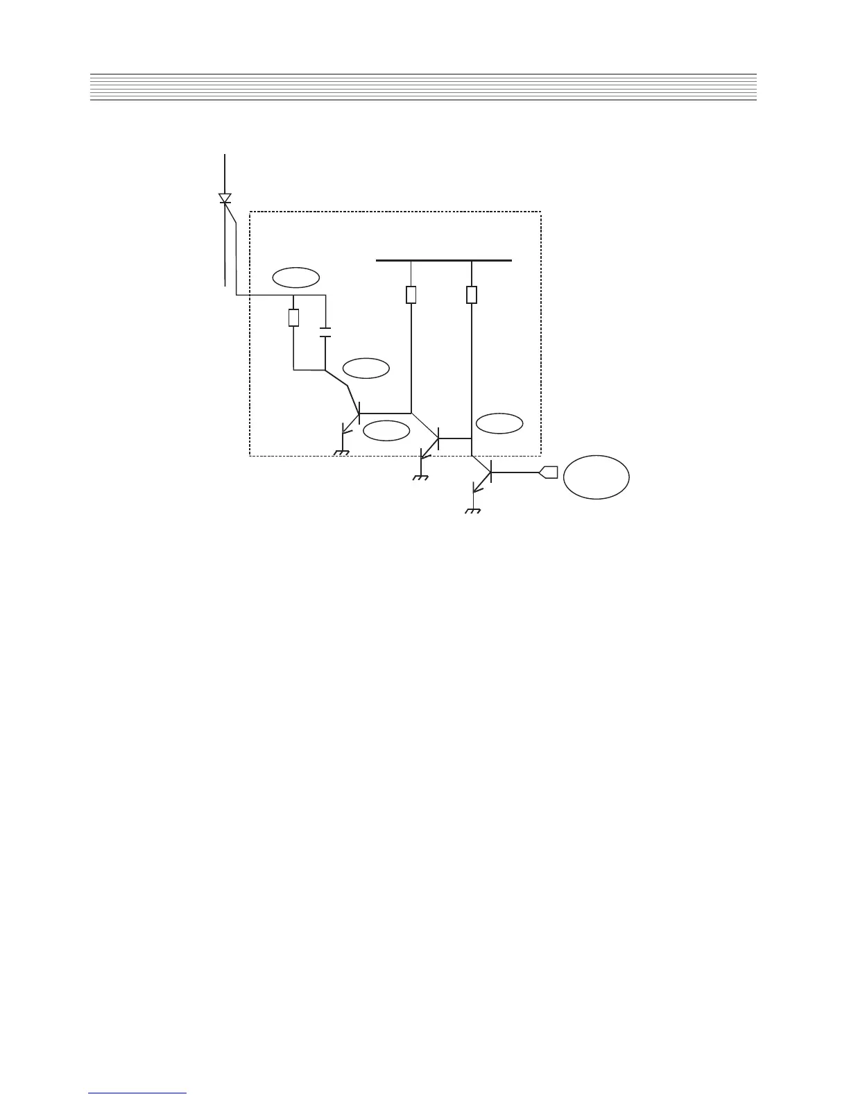
I810 controlled rectifier switching circuit
* TV set stand-by mode operations
-On stand-by mode, I501 microcontroller pin 63 (power) is set to low.
- So, Q809 collector is set to high.
-Then, I810 controlled rectifier gate pin is set to high and I810 is conducting.
- So, current flows from pin 16 SMPS transformer to the ground via I804 optocoupler and Q810
and Q811 transistors (which are conducting).
- In these conditions, I801 delivers pulses on light mode and T801 produces voltages with
reduced power.
- As I810 is conducting, current flows also from pin 16 SMPS transformer to I823 (3.3V
regulator) for I501 com, IR receiver and front mask buttons supply voltage (then, remote
control or front mask buttons can be activated to leave stand-by mode).