Disassembly and Reassembly 3-11
Main Board
Remove the main board as follows.
1.
Save any open files, exit Windows, turn off notebook power, close the LCD panel, unplug
the power cable, and disconnect any peripheral devices.
2.
Remove the secondary battery, hard drive, keyboard, top cover assembly, and USB
connector board.
3.
If installed, remove the PC Card or dummy card from the PC Card bay.
4.
Unplug the LCD panel cables from connectors P20 and P2 on the main board (see the
following figure for connector locations).
5.
Unplug the switch board cable from connector P16 on the main board.
6.
Remove the screws (
A
,
B
,
C
on the figure) fastening the main board to the base.
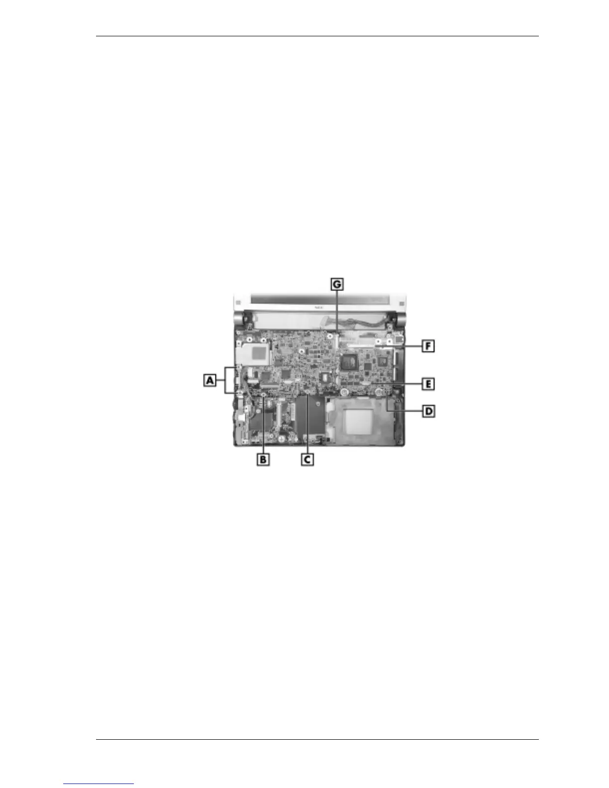
Removing the main board
A – Long Screws (2) E – Switch Board Connector P16
B – Short Black Screw (1) F – LCD Panel Connector P2
C – Short Silver Screw (1) G – LCD Panel Connector P20
D – Main Board
7.
Carefully lift the main board off the base.
You might need to flex the sides of the base to allow clearance for board removal.
When reinstalling the main board, use care to prevent damage to the PC Card ejection lever.
8.
Set the main board on a static-free surface.
If replacing the board, remove and save the processor assembly, memory module, and Mini
PCI board for installation on the new board.