3-12 Disassembly and Reassembly
Processor Assembly
Remove the processor assembly as follows.
1.
Save any open files, exit Windows, turn off notebook power, close the LCD panel, unplug
the power cable, and disconnect any peripheral devices.
2.
Remove the secondary battery, hard drive cover, keyboard, top cover assembly, USB
connector board, and main board.
3.
Lift the processor assembly off its four standoffs on the base. Store the assembly in a static-
free bag.
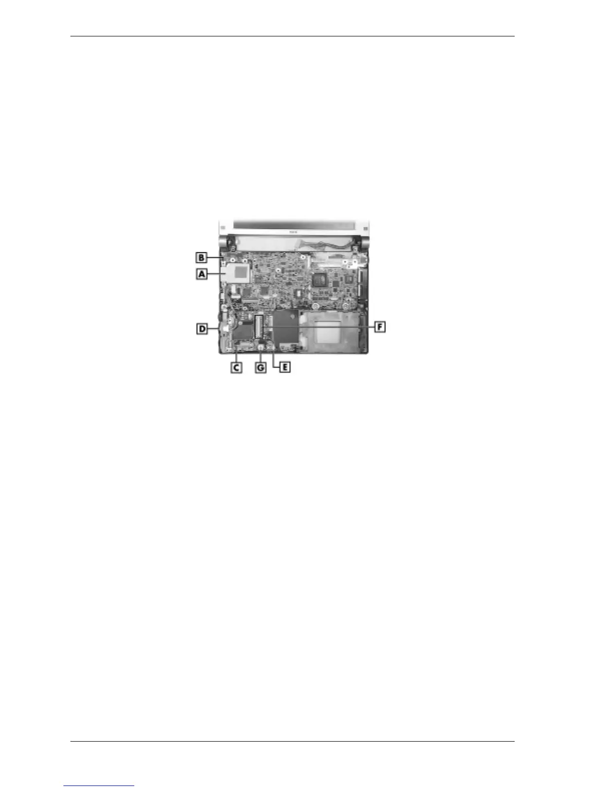
Removing the processor assembly and communication board
A – Processor Assembly D – LAN Connector
B – Processor Standoff (1 of 4) E – Micro Switch Connector P37
C – Communication Board F – Mini PCI Board Connector P32
Communication Board
Remove the communication board as follows.
1.
Save any open files, exit Windows, turn off notebook power, close the LCD panel, unplug
the power cable, and disconnect any peripheral devices.
2.
Remove the secondary battery, hard drive, keyboard, top cover assembly, Mini PCI board,
USB connector board, and main board.
3.
Unplug the following cables from the communication board (see the preceding figure
“Removing the processor assembly and communication board” for cable connector and
component locations):
! LAN connector cable from connector P35
! CMOS battery cable from P36 or, to avoid losing BIOS customized settings, move the
battery off the base, out of the way, without unplugging the cable
! microswitch cable from connector P37.
4.
Remove the screw and standoff fastening the communication board to the base.
5.
Remove the board from the base.