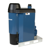
FilterBox
3.2Main components
See Figure1.
1 Extraction arm with hood
2 Enclosure
3 Crank for filter cleaning (FilterBox M)
4 Main filter
5 Collector bin
6 HEPA Filter (Accessory)
7 Fan package including silencer
8 Air outlet
9 Control box and control panel
10 Mains fuse: Max. 16 A
3.3Control panel
See Figure2.
A,B,C,D: Show how dirty the main filter is.
E: Shows when there is a warning or an alarm.
F: Fan status.
G: LCD and navigation buttons
H: Loudspeaker for alarms.
I: Fuses for the electrical outlet K.
J: Outlet for pneumatic power tools.
K: Outlet (1-phase) for electrical power tools.
L: Main switch.
M: Operation timer.
S1: Button to start or stop the fan.
S2: Start or stop filter cleaning.
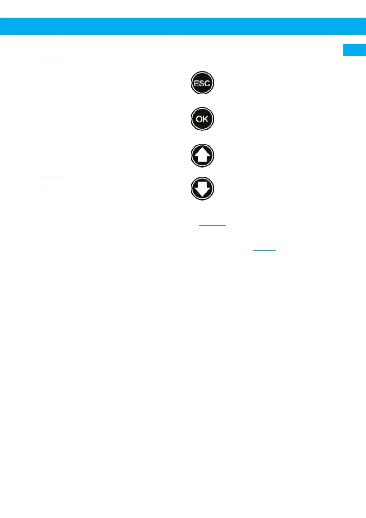
3.4LCD and navigation buttons
3.4.1Navigation button functions
• Open the main menu.
• Move backwards in the menu.
• Open submenu.
• Select setting for change (indicated
with ‘*’).
• Confirm change.
• Scroll up in the menu (position indic-
ated with ‘>’).
• Increase or change setting.
• Scroll down in menu (position indic-
ated with ‘>’).
• Decrease or change a setting.
3.4.2Menu structure
See Figure15.
3.5Dimensions
Measures are shown in Figure3.
A FilterBox N24 fan
B FilterBox N27/N29 fan
C FilterBox Wall
EN
25

 Loading...