Installation
Hardware setup
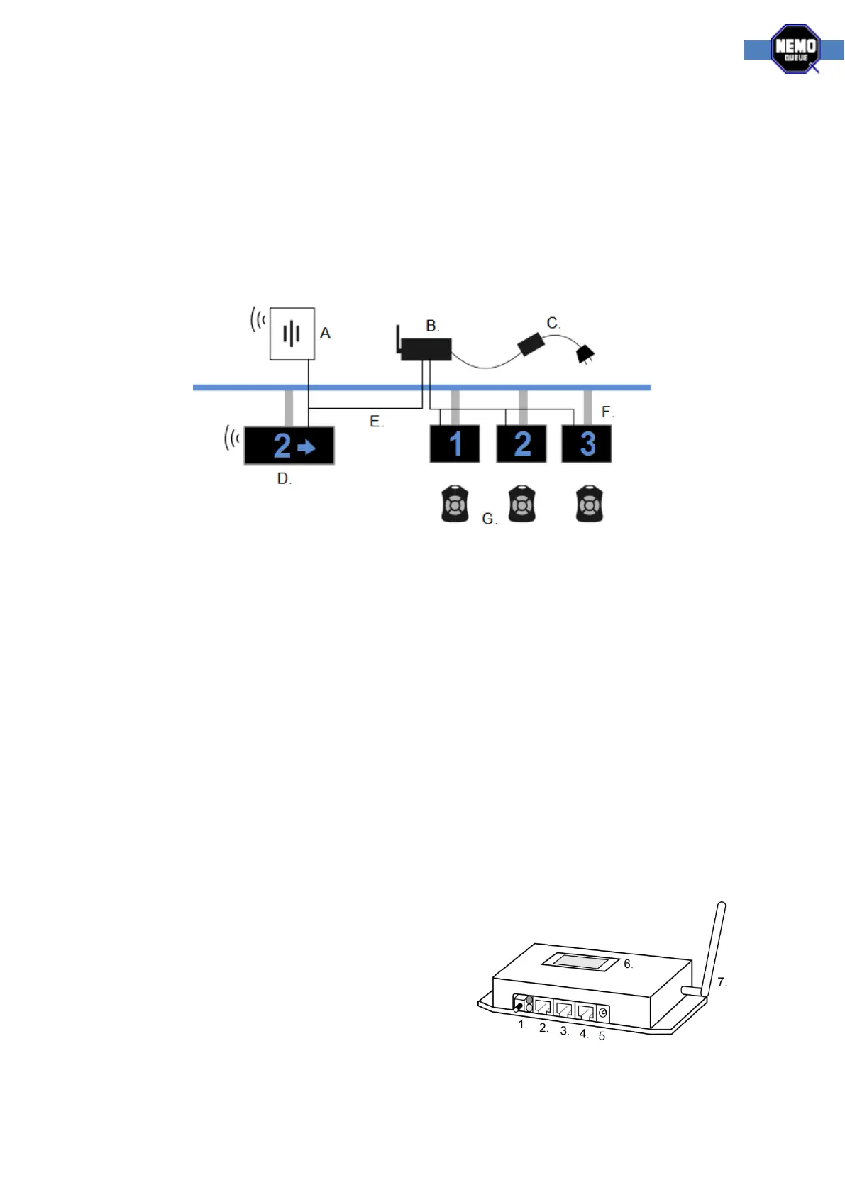
All components are connected with standard cat5 network cables (E). The power supply has a
standard c13 power cable (C). Displays are hung using Nemo-Q pipes and connectors or wall
mounting brackets (F). Main display (D), indicators (F) and speakers (A) all run on the same cables
and can be serially connected. A Nemo-Q MOA modular splitter unit is used for systems with over 10
displays connected. NQ Receiver (B) and speakers (A) have holes for mounting on a wall or cable
channel mounting sheet.
NQ Displays
The main display is a special TCD with buzzer (item no. 11603-71E). Configuration of the dipswitches
is as followed:
Function dips = all off, address dips = value 33.
Indicators must be TCD displays. Configuration of the dipswitches is as followed:
Function dips = 4 on, address dips = the corresponding workstation number
NQ Receiver
We use a dipswitch to distinguish what system the NQ Receiver is working as. The dipswitch
configuration for the Single-Q system is as follows:
- All switches off, value of 0.
The image below and the labels on the NQ Receiver show you where the cables go.
1. Link button, used for adding new NQ Remote
controls to the system
2. Display and speaker, RJ45
3. Display and speaker, RJ45
4. Media out, RS232
5. Power
6. Small display, used for configuring the system
(the main display can be used as well)
7. Antenna, packed separately and screwed on