5
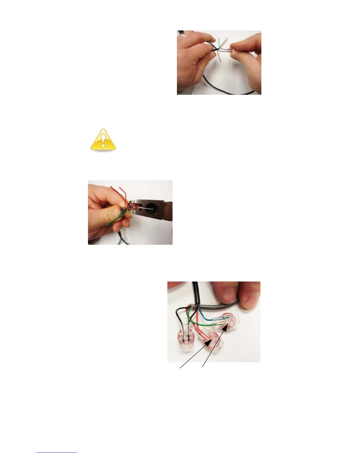
Figure 10 Seating Connector Wires
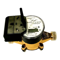
Figure 11 UR Crimping Tool
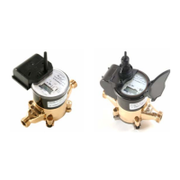
Figure 12 Improper Connections
5 Squeeze the connector firmly with the proper crimping tool
until you hear a pop and gel oozes out the end of the
connector.
2 Take one non-stripped black
wire from the pigtail and one
from the receptacle/MIU by
inserting the wires into the
Scotchlok connector until
fully seated. See Figure 10.
Do not strip the colored insulation from the
wires or strip and twist the bare wires prior to
inserting in the connector. Insert the insulated
colored wires directly into the Scotchlok
connector.
3 Place the connector red
cap side down between the
jaws of the UR crimping
tool as shown in Figure 11.
Refer to Table 3 on
page 10 for part numbers.
4 Check to ensure that the
wires are still fully seated
in the connector before
crimping the connector.
Figure 12 illustrates
improper connections
due to wires not being
fully seated.
Red and green wires not fully seated