6
6 Repeat steps one through five for each color wire. See
Table 2 for the wiring configuration to connect Neptune MIUs
or competitive MIUs to the E-CODER.
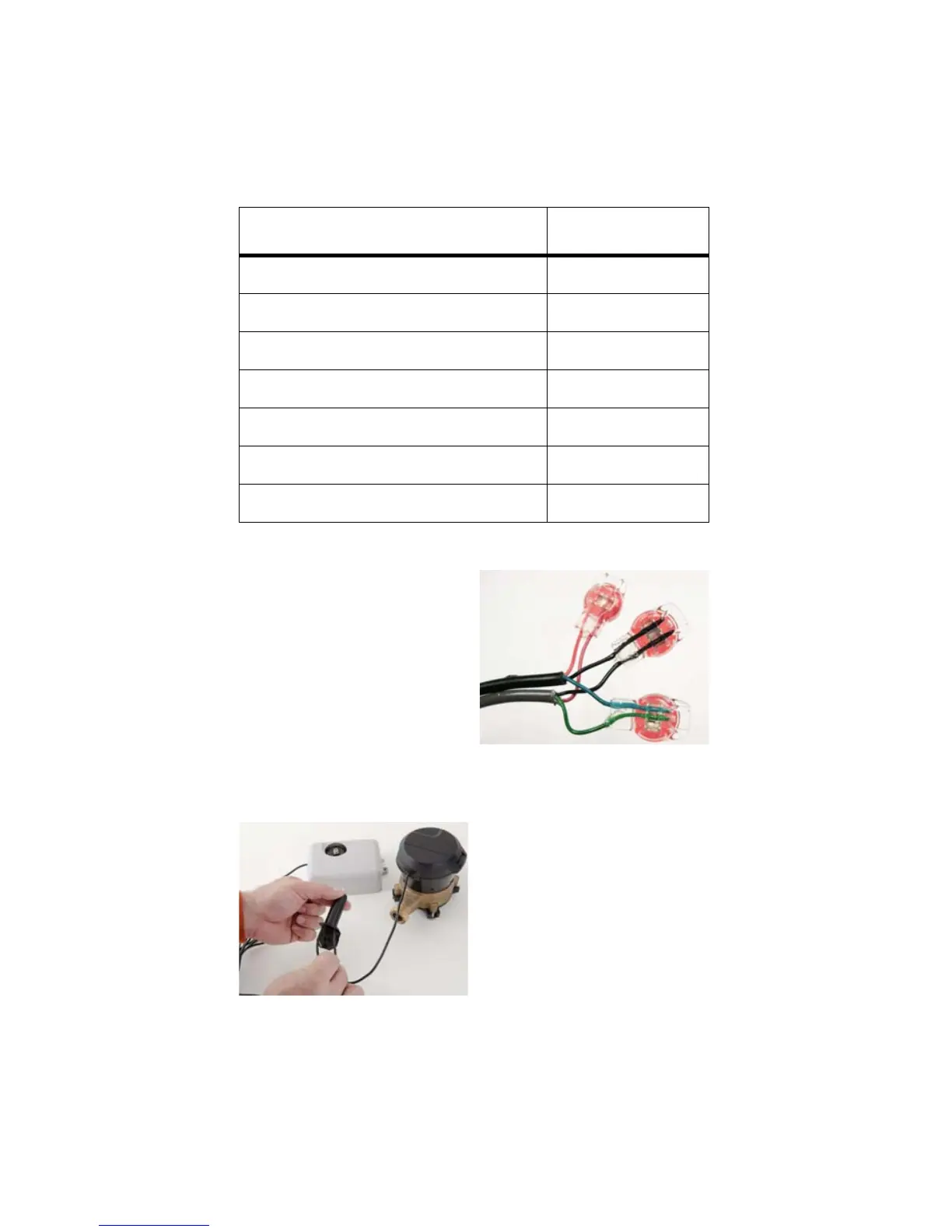
Figure 13 Three Color Wires Connected
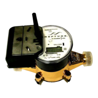
Figure 14 Splice Tube
Table 2 Color Codes for Wires
MIU Wire Color / Encoder Terminal MIU Type
Black/B Green/G Red/R R900
Black/B Green/G Red/R R450
Black/G Green/R Red/B Sensus
Black/B White/G Red/R Itron
Black/G White/R Red/B Aclara
Black/G Green/B Red/R Elster
Black/G Green/R Red/B Badger
7 After all three color wires
have been connected, read
the encoder register to
ensure proper connections,
and the receptacle/MIU is
functioning properly. See
Figure 13.
8 Take all three connected
Scotchloks and push into
the splice tube until fully
covered by the silicone
grease. See Figure 14.