N E T A F I M T E C H L I N E
®
C V D E S I G N G U I D E
N E T A F I M T E C H L I N E
®
C V D E S I G N G U I D E
BASIC
DESIGN
STEPS
(continued)
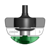
• To reduce the number of glue joints, saddles or insert fittings in a header, transition to Techline CV
and Techline fittings to make up subheaders.
• Make sure to follow the guideline of not exceeding 5 GPM in the “sub-header” zone.
OTHER GRID LAYOUT CONSIDERATIONS:
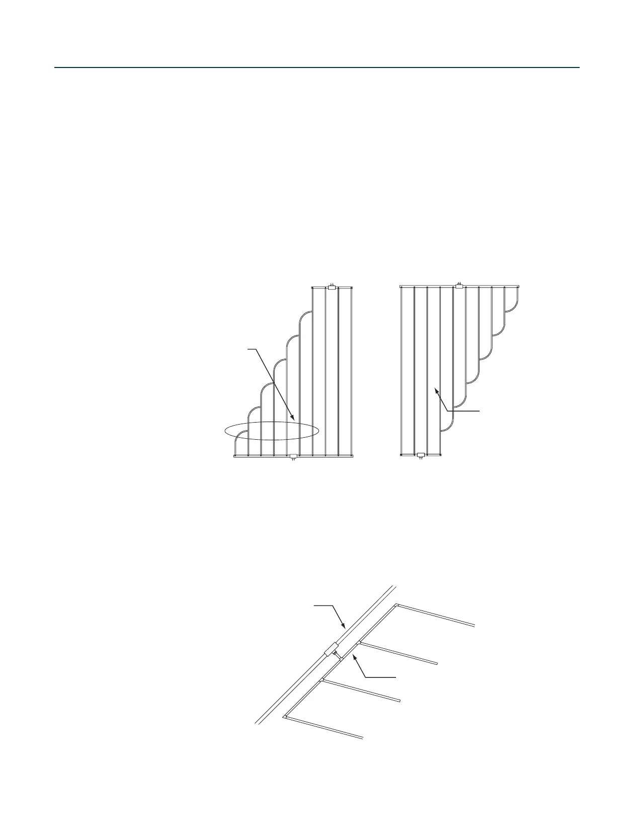
• When branching out or joining rows of Techline CV, one of two rules apply:
Rule #1: When branching out Techline CV from the supply header, add up all “branched out”
dripperline and check it against the maximum lateral length listed in Table 2.
Rule #2: When joining laterals from the supply header, check only the longest lateral against the
maximum allowable in Table 2.
Exhaust Header
Supply Header
Check longest
lateral agains
Table 2 for
maximum
lateral length.
Joining
Techline CV Laterals
Exhaust Header
Supply Heade
Total the combined
length of these
Techline CV laterals
and compare it
against the maximum
lateral length allowed
in Table 2.
Branching Out
Techline CV Laterals
Techline fittings
and dripperline
PVC or
Poly Piping
Creating Sub-Headers to
Reduce Glue/Saddle Joints