N E T A F I M T E C H L I N E
®
C V D E S I G N G U I D E
N E T A F I M T E C H L I N E
®
C V D E S I G N G U I D E
BASIC
DESIGN
STEPS
(continued)
Calculating Total Zone Water Demand
• Multiply Total Feet x 12” = Total inches of Techline CV
• Total Inches of Techline CV ÷ Dripper Spacing = Number of Drippers
• Multiply Number of Drippers x Dripper Flow Rate (GPH) = Total GPH Flow
• Total GPH Flow ÷ 60 = Total GPM in the Zone
Example:
Ten 100ʼ rows of Techline CV with Dripper Spacing of 18”, Flow Rate is 0.6 GPH.
100ʼ x 10 = 1,000ʼ
1,000ʼ x 12” = 12,000” 12,000” ÷ 18” = 667 Drippers
667 Drippers x 0.6 GPH = 400 GPH Total Flow
400 GPH ÷ 60 = 6.67 GPM Flow in the Zone
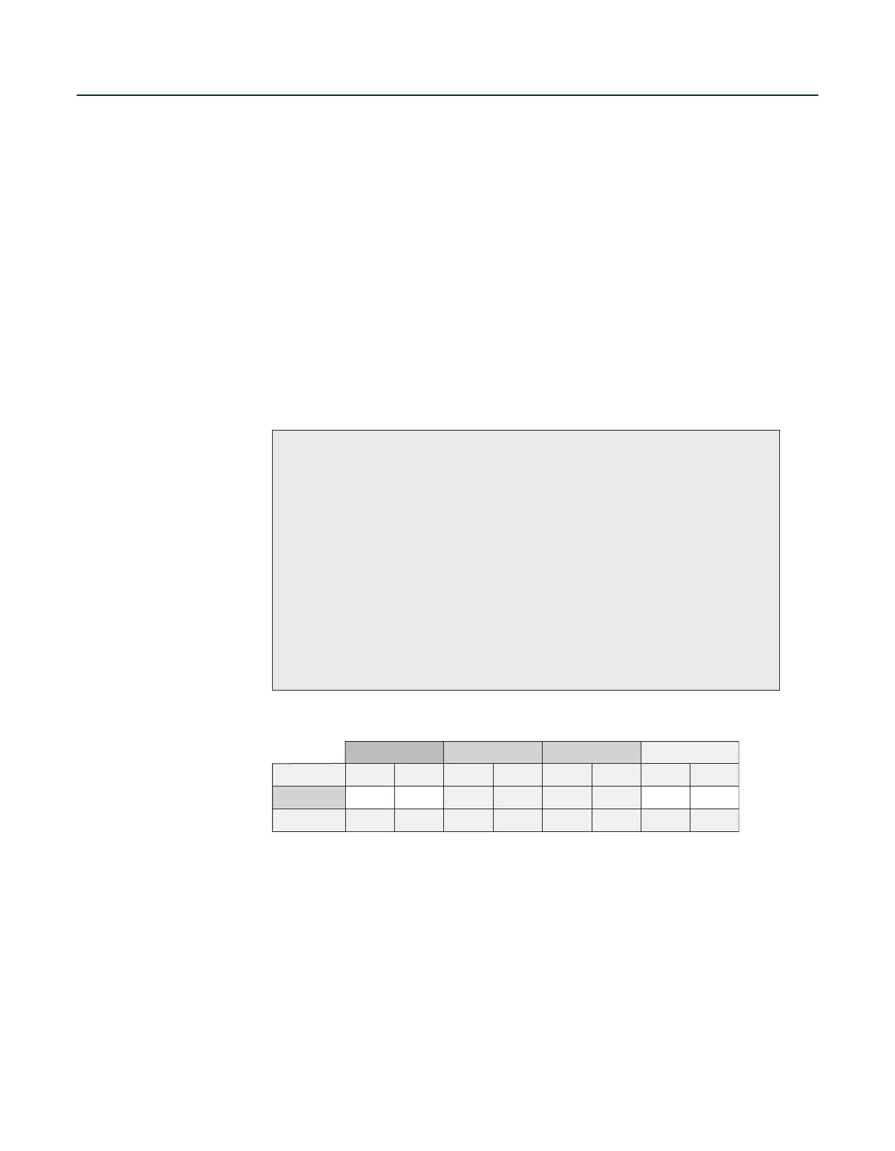
0.26 GPH Dripper 0.9 GPH Dripper
26.40 GPH
17.58 GPH
Not Available
0.44 GPM
0.29 GPM
Not Available
0.4 GPH Dripper
40.OO GPH
26.67 GPH
Not Available
0.67 GPM
0.44 GPM
Not Available
61.00 GPH
41.00 GPH
31.00 GPH
92.00 GPH
61.00 GPH
46.00 GPH
1.53 GPM
1.02 GPM
0.77 GPM
12"
18"
24"
0.6 GPH Dripper
1.02 GPM
0.68 GPM
0.51 GPM
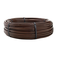
TECHLINE
®
CV
Flow
(per 100 feet)
DRIPPER SPACING
TABLE 3
ZONE WATER REQUIREMENTS:
• Once the Techline CV is laid out, we need to identify total zone flow. This will help determine
mainline, submain as well as supply and exhaust header sizing, valve, filter, and pressure regulator
selection.
• There are two ways to determine the flow in a Techline CV zone.
• Because Techline CV is pressure-compensating, the flow rate per 100' is the same over a wide
pressure range.
• Table 3 shows an easy way to determine total zone flow:
– Add up the amount of Techline CV
(in hundreds of feet) and
– Multiply that figure by the corresponding dripperline GPM to determine zone flow.