Physical Description
12
NETGEAR GS110T Smart Switch
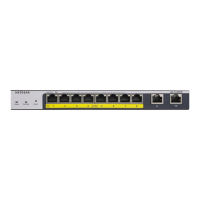
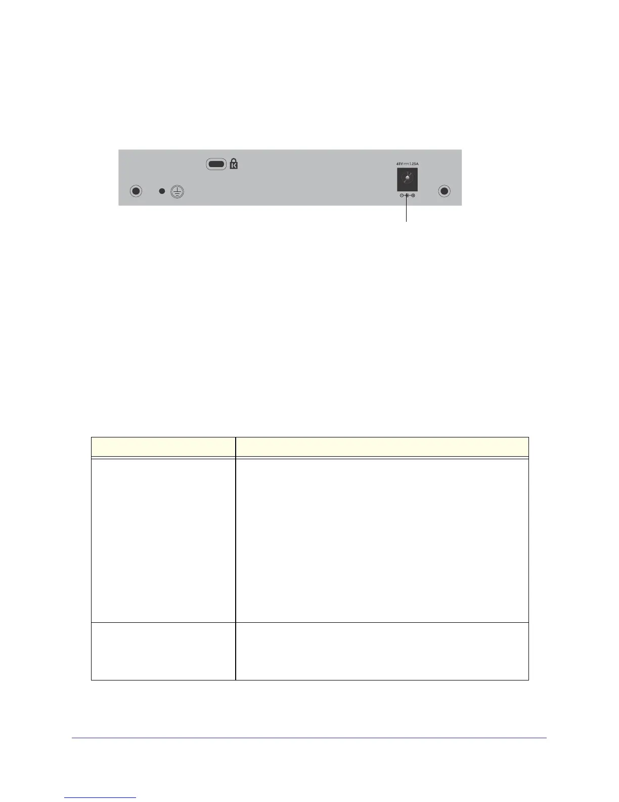
GS110T Back-Panel Configuration
Figure 3 illustrates the GS110T back panel.
Power Connector
Figure 3. GS110T Back Panel
The back panel contains the following:
• External 12V/1A power adapter for the GS110T
LED Designations
Port LEDs
Table 1 describes the RJ-45 and SFP port LED designations. There are two LEDs for each
RJ-45 port.
Table 1. Port LEDs
LED Designation
Speed/Link/Activity 100 Mbps Link/ACT LED (Left LED):
• Off = No 100 Mbps link is established on the port.
• Solid Green = A valid 100 Mbps link is established on the port.
• Blinking Green = Packets transmission/received on the port.
10 Mbps Link/ACT LED (Right LED):
• Off = No 10 Mbps link is established on the port.
• Solid Green = A valid 10 Mbps link is established on the port.
• Blinking Green = Packets transmission/received on the port.
1000 Mbps Link/ACT LED (Both LEDs):
• Off = No 1000 Mbps link is established on the port.
• Solid Green = A valid 1000 Mbps link is established on the port.
• Blinking Green = Packets transmission/received on the port.
SFP Port Indicate LED • Off = No link is established on the port.
• Solid Green = A valid link is established on the port.
• Flashing Green = Packet transmission or reception is occurring on
the port.
Each SFP port has its own indication LED.
 Loading...