Do you have a question about the NETGEAR GS110TUP and is the answer not in the manual?
Provides a general description of the switch's capabilities and connectivity options.
Details the key hardware features of the switch, including port types and PoE capabilities.
Explains the different methods available for managing and configuring the switch.
Provides essential safety guidelines and precautions for operating the switch.
Details the hardware components and specifications for the GS110TUP model.
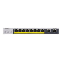
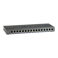
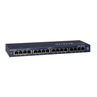
Describes the front panel layout, including ports and LEDs for the GS110TUP model.
Explains the meaning of each LED indicator on the front panel of the GS110TUP.
Details the back panel components of the GS110TUP, including connectors and slots.
Details the hardware components and specifications for the GS710TUP model.
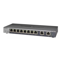
Describes the front panel layout, including ports and LEDs for the GS710TUP model.
Explains the meaning of each LED indicator on the front panel of the GS710TUP.
Details the back panel components of the GS710TUP, including connectors and slots.
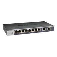
Describes the various hardware interfaces available on the switch for connectivity.
Details the RJ-45 ports for 10/100/1000M BASE-T Ethernet connectivity.
Explains the SFP uplink port for fiber connectivity and compatible modules.
Describes the functionality and operation of the recessed multi-function reset button.
Provides an overview of Power over Ethernet Plus Plus (PoE++) technology and its support.
Illustrates a sample configuration for desktop switching using PoE++ and PoE+ devices.
Details using Ultra60 PoE++ for high-resolution surveillance and security cameras.
Explains the application of Ultra60 PoE++ for powering smart building LED lighting.
Details site requirements, including mounting, access, power, cabling, and environment.
Explains how to protect the switch from electrostatic discharge (ESD) during handling.
Guides on how to unpack the switch and verify package contents for both models.
Provides instructions for installing the switch on a flat surface or in a rack.
Instructions for placing the switch on a flat surface using rubber footpads.
Instructions for mounting the switch into a standard 19-inch network rack.
Detailed steps for wall-mounting the GS110TUP model horizontally or vertically.
Instructions for mounting the GS110TUP to a pole or other surface using VESA mounts.
Procedure for installing an optional SFP transceiver module into the SFP uplink port.
Guides on connecting various devices, including PoE, PoE+, and non-PoE, to the switch ports.
Steps to perform a thorough check of the installation before applying power.
Instructions for applying power to the switch and checking the status LEDs.
Explains initial steps for managing and configuring the switch after installation.
A table listing common symptoms, their possible causes, and suggested solutions.
Tips and solutions for resolving issues related to Power over Ethernet (PoE) functionality.
Provides additional suggestions for resolving problems not covered in the main troubleshooting chart.
| Switch type | Managed |
|---|---|
| Switch layer | L2/L3 |
| Power connector | DC-in jack |
| SFP module slots quantity | 1 |
| Installed SFP modules quantity | - |
| Basic switching RJ-45 Ethernet ports type | Gigabit Ethernet (10/100/1000) |
| Basic switching RJ-45 Ethernet ports quantity | 10 |
| Product color | White |
| Rack mounting | Yes |
| LED indicators | Activity, Link, PoE, Power, Speed |
| Number of fans | 0 fan(s) |
| Heat dissipation | 945 BTU/h |
| Operating altitude | 0 - 3000 m |
| Storage temperature (T-T) | -20 - 70 °C |
| Operating temperature (T-T) | 0 - 40 °C |
| Operating relative humidity (H-H) | 0 - 95 % |
| Total Power over Ethernet (PoE) budget | 240 W |
| Power over Ethernet plus (PoE+) ports quantity | 8 |
| Input current | 4.7 A |
| DC input voltage | 54 V |
| Power consumption (max) | 276.8 W |
| Package type | Gift box |
| Master (outer) case width | 402 mm |
| Master (outer) case height | 357 mm |
| Master (outer) case length | 453 mm |
| Master (outer) case weight | 20140 g |
| Harmonized System (HS) code | 85176990 |
| Quantity per master (outer) case | 6 pc(s) |
| Jumbo frames | 10000 |
| Forwarding rate | 14.8 Mpps |
| MAC address table | 8000 entries |
| Packet buffer memory | 0.512 MB |
| DHCP features | DHCP client, DHCP snooping |
| Security algorithms | SSL/TLS |
| Queue scheduling algorithms | Weighted Round Robin (WRR) |
| Access Control List (ACL) IPv6 entries | 100 |
| 10G support | No |
| Number of VLANs | 64 |
| Networking standards | IEEE 802.1D, IEEE 802.1Q, IEEE 802.1ab, IEEE 802.1s, IEEE 802.1w, IEEE 802.1x, IEEE 802.3ad, IEEE 802.3x |
| Number of multicast groups filtered | 256 |
| Noise level | 0 dB |
| Mean time between failures (MTBF) | 695508 h |
| Depth | 101 mm |
|---|---|
| Width | 236 mm |
| Height | 27 mm |
| Weight | 630 g |