Back Panel With Connectors, Buttons, and a Port
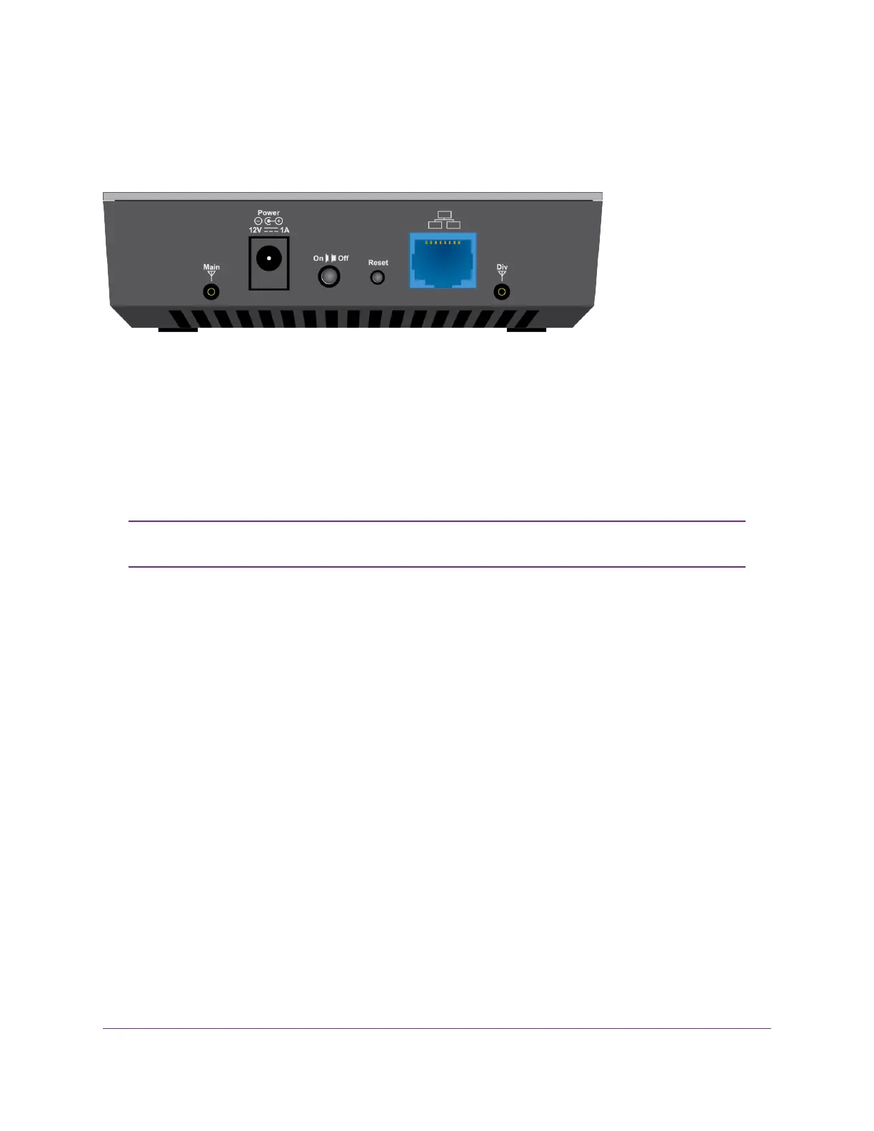
The following figure shows the port, connectors, and buttons on the back panel of the modem.
Figure 4. Modem components on the back panel
From left to right, the back panel of the modem provides the following components:
• Connector for an external antenna. One switched RF connector for an optional external antenna (the
external antenna requires two inputs).
• DC connector. A DC connector to connect the AC power supply that is included in the package.
• On/Off button. An On/Off button to control power to the modem.
After you press the On/Off button, wait about 30 seconds for the modem to complete
the boot process.
Note
• Reset button. A recessed Reset button to return the modem to factory default settings.
• Gigabit Ethernet port. One blue RJ-45 Gigabit Ethernet port to connect a router, WiFi router, Ethernet
switch or hub, or single computer.
• Connector for an external antenna. Another switched RF connector for an optional external antenna
(the external antenna requires two inputs).
Modem Label
In addition to the default URL and password to access the modem’s web pages, the modem label on the
bottom panel shows the following information:
• Serial number (SN)
• Stockkeeping unit (SKU) number
• MAC address
• IMEI (International Mobile Station Equipment Identity)
Introduction and Hardware Overview
12
LTE Modem LB1120 and LB1121