GS700TP Hardware Installation Guide
Physical Description 2-9
v1.0, January 2007
System LEDs
The following table describes the system LED designations.
Table 2-2. System LEDs
LED Designation
MAX POE LED • Solid Yellow - Indicates that less than 7W of PoE power is available.
• Flashing Yellow - Indicates the PoE MAX LED was active in the
previous two minutes.
• Off - Indicates that there is at least 7W of PoE power available for
another device
1~24/48 Port LED mode select
LED
• Solid Green - LED Mode in Ethernet LED Mode (default).
• Solid Yellow- LED Mode in PoE LED Mode
Power LED • Solid Green - Power is supplied to the switch and is operating
normally.
• Off - Power is disconnected.
Fan LED • Yellow - The fan is not operating normally.
• Off - The fan is operating normally.
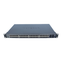
Device Hardware Interfaces
RJ-45 Ports
RJ-45ports are auto-sensing ports. When inserting a cable into an RJ-45 port, the switch
automatically ascertains the maximum speed (10, 100 or 1000 Mbps) and duplex mode (half- or
full-duplex) of the attached device. All ports support only unshielded twisted-pair (UTP) cable
terminated with an 8-pin RJ-45 plug.
To simplify the procedure for attaching devices, all RJ-45 ports support Auto Uplink. This
technology allows attaching devices to the RJ-45 ports with either straight-through or crossover
cables. When inserting a cable into the switch’s RJ-45 port, the switch automatically:
• Senses whether the cable is a straight-through or crossover cable.
• Determines whether the link to the attached device requires a “normal” connection (such as
when connecting the port to a PC) or an “uplink” connection (such as when connecting the
port to a router, switch, or hub).

 Loading...