Surgical Procedures 47
RNS
®
System User Manual
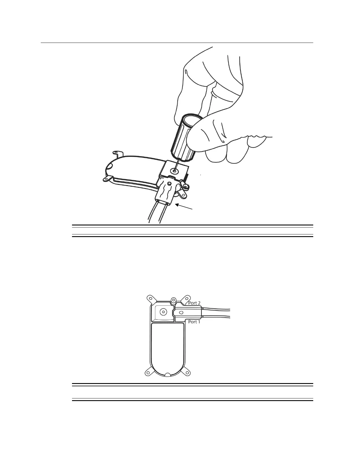
Figure 16: Secure the connector cover and lead(s) to the RNS
®
Neurostimulator using the torque driver.
10. Place the lead strain relief over the proximal ends of the leads extending from the connector
cover (Figure 16) and attach it to the post.
11. Cover the wand with a sterile bag and position it over the neurostimulator.
12. Record the lead information, serial number(s), and corresponding neurostimulator port
number(s) on the P
ATIENT/PRODUCT tab of the programmer.
Figure 17: RNS
®
Neurostimulator port #1 and #2 locations. Port #1 is located towards the center of the
neurostimulator and port #2 is closer to the edge.