C70 Digital Readout System
Segmented Error Compensation
SETUP, Segmented Error Compensation
NOTES
Up to 99 segments can
be defined per axis
To take advantage of
Segmented Error
Compensation, you will
need access to a high
accuracy standard, such
as a laser measuring
system.
Error Compensation
initially defaults to off,
with no points set.
If Error Compensation is
set to Off after
Correction Points have
been set, the data is
retained, but not applied.
When Segmented Error
Compensation is set to
On again, the data will
be re-applied.
This procedure must be
carried out in strict
sequence, and in full, to
be valid. There must be
no reversals in direction.
Pressing select key
at steps 1, 2 or 3, will
display the current
uncorrected position
relative to the (Starting
Point).
Do not worry about the
direction of the standard
measurement. eg. 678.9
and -678.9 are treated
the same.
Pressing
will clear
an entry one character at
a time.
After an entry has been
completed by pressing
, pressing
will take you back one
step at a time.
Newall Measurement Systems Ltd 11
If one or more axes are set to Segmented Error Compensation, then the following procedure should
be followed to configure the compensation for each of those axes.
Identification of Correction Parameters
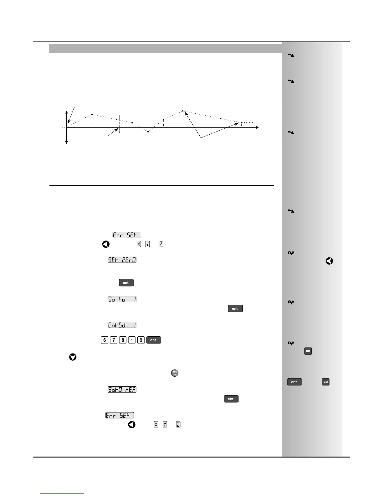
The scale travel is broken down into a number of user-defined segments, each with its own correction
factor, measured against a high-accuracy standard. The following parameters need to be identified:
error
travel
Starting Point - zero
Correction Points
Reference Point
0
1
2
3
4
5
6
Each Correction Point is measured with respect to the Starting Point - zero - which is usually set close
to one end of the scale. The Reference Point can be set anywhere along the scale, and does not need
to coincide with either the absolute datum or any of the correction points. However, it may be convenient
to make the absolute datum and the reference point the same.
Setting the Correction Points
As you follow the steps below, it is essential to take the following precaution:
Always approach the Starting Point, Correction Points and Reference Point from the same
direction. If you do not, then the size of the tool or probe will render the measurement inaccurate.
• Set one or more axes to Segmented Compensation as described on page 10.
The display should show, .
• Press the Select Key next to the , or to enter the setup procedure for each axis to be
configured.
The display changes to .
1 Set the machine to the point you have chosen to the Starting Point, and zero the high-accuracy
standard at this point. Press .
2 The display changes to .
Set the machine to the point you have chosen to be Correction Point 1. Press .
3 The display changes to .
Enter the distance from the Starting Point, as measured by the standard.
For Example: Press to enter a Correction Point of 678.9.
The C70 will calculate and display the correction factor for this point.
• Press to go to the next point.
Repeat steps 2 and 3 for each Correction Point.
When all correction points have been entered, press .
4 The display changes to .
Set the machine to the point you have chosen as the Reference Point. Press .
5 The display returns to .
If required, press the Select Key next to , or to enter the setup procedure for another
axis.