Linear Error Compensation
SETUP, Linear Error Compensation C70 Digital Readout System
NOTES
The Correction Factor
cannot be established
while in Setup Mode.
Carry out the
measurements in Normal
Operating Mode, then
enter Setup Mode to set
the Correction Factor.
Only values between
-9999 and 9999 are
allowed.
If you make a mistake
while entering a number,
pressing will clear
the entry one character
at a time.
Newall Measurement Systems Ltd12
A single constant correction factor for each axis is applied to all displayed measurements.
If one or more axes are set to Linear Error Compensation, then the following procedure should be
followed to configure the compensation for each of those axes.
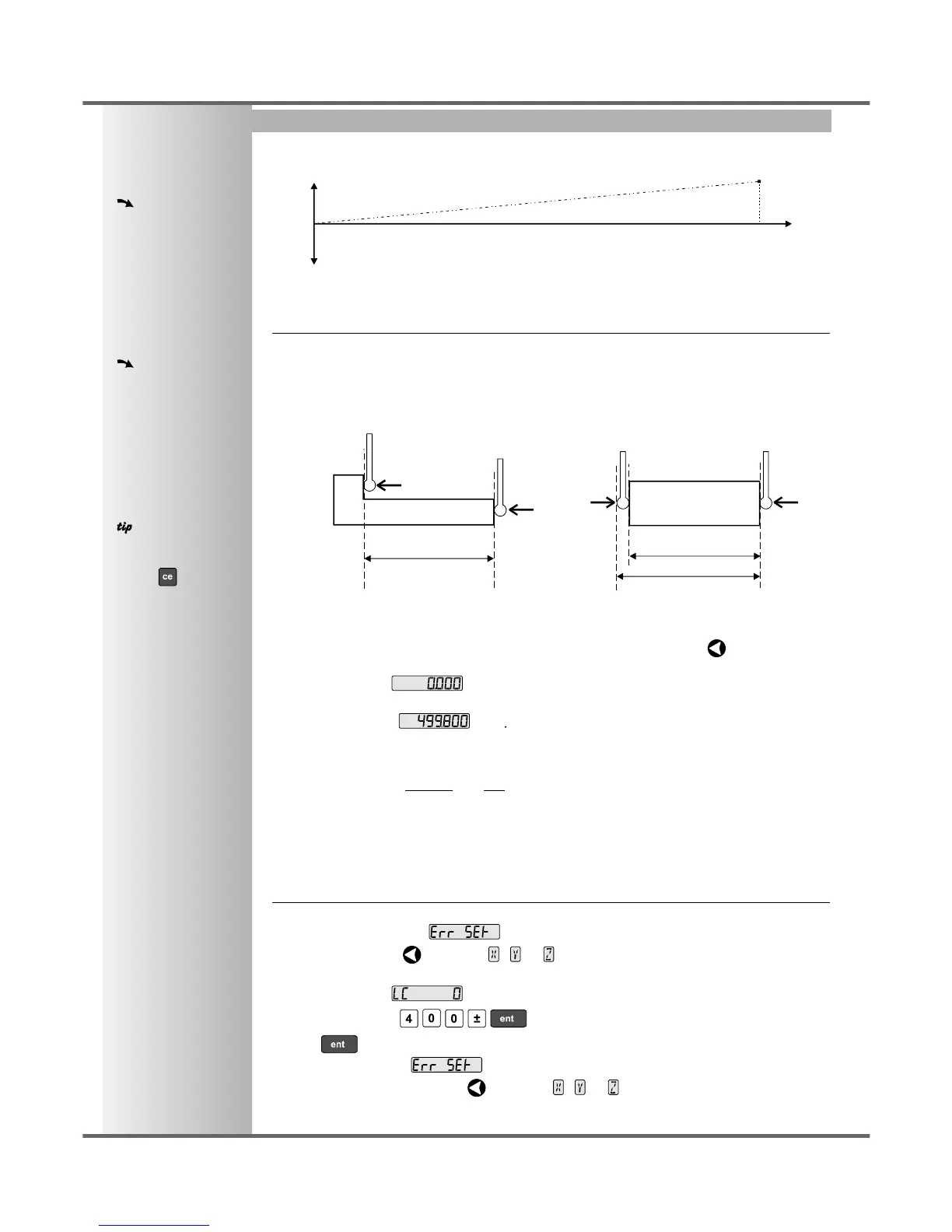
Calculating the Correction Factor
As you follow the steps below, it is essential to take the following precaution:
Either: Use a stepped standard, and approach each edge from the same direction.
Or: If you must approach each edge from opposite directions, then subtract the width of
the tool or measuring probe from the value displayed on the C70.
For Example: To check the scale against a standard which is exactly 500mm wide:
• Set the tool or proble to one edge of the standard, and press the Select Key for the axis to be
corrected.
The display shows .
• Set the tool or probe to the other edge of the standard.
The display shows , .
• Calculate the correction factor:
error = 500.000 - 499.8 = 0.2mm
Correction Factor = = x 1,000,000 = +400 ppm (parts per million)
This value displayed on the C80 needs to be increased to match the standard, so this is a positive
correction factor. If the display had shown 500.2 for the same standard, the correction factor
would be negative -400 ppm.
Setting the Correction Factor
• Set one or more axes to Linear Error Compensation as described on page 10
The display should show, .
• Press the Select Key next to the , or to enter the setup procedure for each axis to be
configured.
The display shows , or a previously entered value.
• For Example: Press to enter a Correction Factor of -400 ppm.
• Press again.
The display returns to .
If required, press the Select Key next to the , or to enter the setup procedure for
another axis.
0.2
500
error
standard
error
travel
standard distance
measured distance
= standard distance
tool or
probe
tool or
probe
measured distance