B
briancameronAug 13, 2025
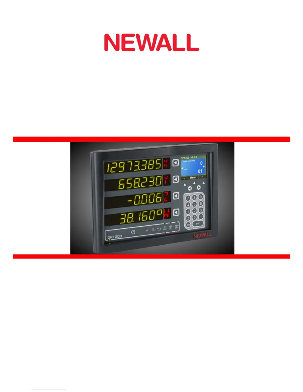
How to fix ‘no Sig’ or ‘SIG FAIL’ on Newall dp1200 display?
- EEmily Mcdowell MDAug 13, 2025
If you see ‘no Sig’ or ‘SIG FAIL’ on the display, it means the unit isn't receiving a proper signal from the encoder. Here's what you can do: * Check that the encoder connections are secure. * Inspect the connectors and the encoder for any damage. * Try switching the DP1200 off and then on again. * Swap the encoder to another axis to determine if the encoder or the DP1200 is the cause of the problem.