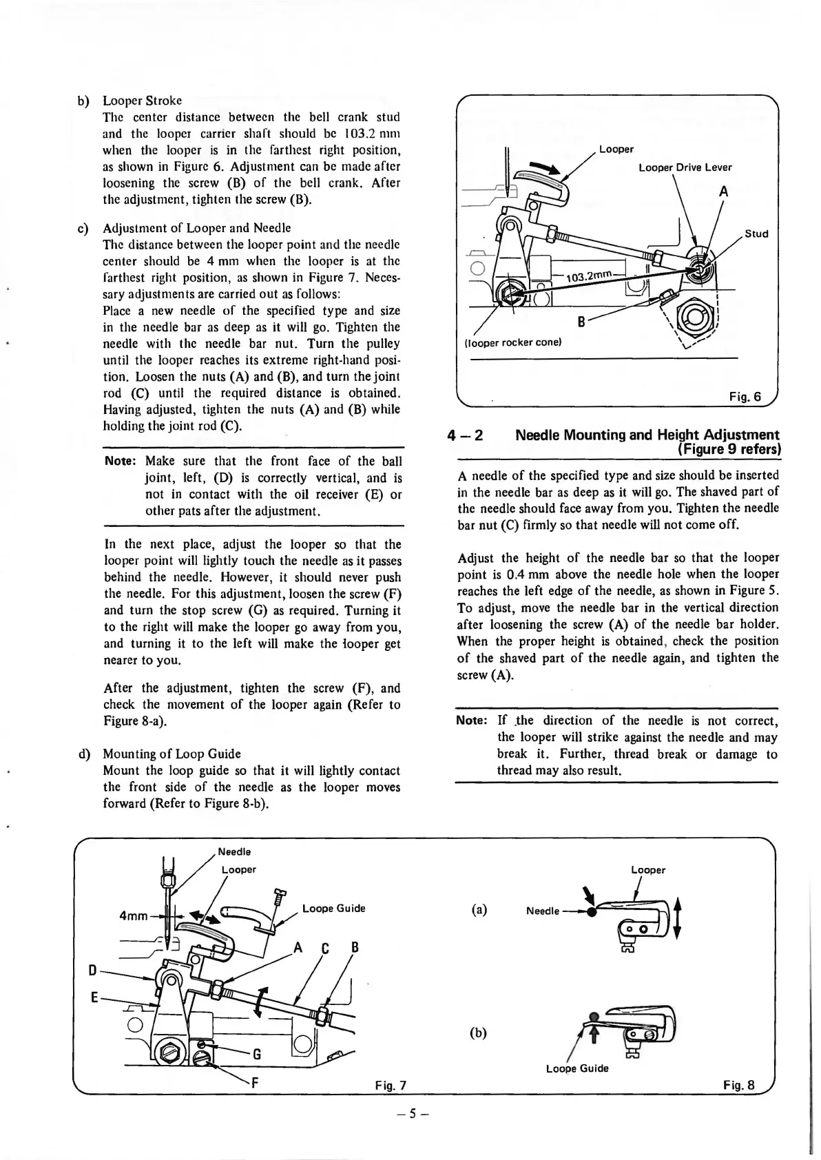
b) Looper Stroke
The center distance between the bell crank stud
and the looper carrier shaft should be
I 03.2 mm
when the looper
is
in the farthest right position,
as
shown
in
Figure 6. Adjustment can be made after
loosening the screw (B)
of
the bell crank. After
the adjustment, tighten the screw (B).
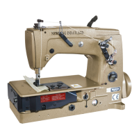
c) Adjustment
of
Looper and Needle
The distance between the looper point and the needle
center should
be
4 mm when the looper
is
at the
farthest right position,
as
shown in Figure 7. Neces-
sary adjustments are carried
out
as
follows:
Place a new needle
of
the specified type and size
in
the needle bar as deep as it will go. Tighten the
needle with the needle bar nut. Turn the pulley
until the looper reaches its extreme right-hand posi-
tion. Loosen the nuts (A) and (B), and turn the joint
rod (C) until the required distance
is
obtained.
Having adjusted, tighten the nuts
(A)
and (B) while
holding the joint rod (C).
Note: Make sure that the front face
of
the ball
joint,
left, (D)
is
correctly vertical, and
is
not in contact with the oil receiver (E)
or
other pats after the adjustment.
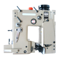
In the next place, adjust the looper so that the
looper point will lightly touch the needle as it passes
behind the needle. However,
it
should never push
the needle. For this adjustment, loosen the screw
(F)
and turn the stop screw (G)
as
required. Turning it
to the right will make the looper
go
away from you,
and turning it to the left will make the iooper get
nearer to you.
After the adjustment, tighten the screw
(F),
and
check the movement
of
the looper again (Refer to
Figure 8-a).
d) Mounting
of
Loop Guide
0
E
Mount the loop guide so that
it
will lightly contact
the front side
of
the needle as the looper moves
forward (Refer to Figure 8-b).
Loope
Guide
Fig. 7
-5-
Looper
Looper Drive Lever
Stud
(looper
rocker cone)
4-2
Fig. 6
Needle Mounting and Height Adjustment
(Figure 9 refers)
A needle
of
the specified type and size should be inserted
in
the needle bar as deep as it will go. The shaved part
of
the needle should face away from you. Tighten
the
needle
bar
nut
(C) firmly so that needle will
not
come off.
Adjust the height
of
the needle bar
so
that the looper
point
is
0.4 mm above the needle hole when
the
looper
reaches the left edge
of
the needle,
as
shown in Figure
5.
To
adjust, move the needle bar in the vertical direction
after loosening the screw (A)
of
the needle bar holder.
When the proper height
is
obtained, check
the
position
of
the shaved part
of
the needle again, and tighten the
screw (A).
Note:
If
_the
direction
of
the needle
is
not
correct,
the looper will strike against the needle and may
break it. Further, thread break or damage to
thread may also result.
(a)
Needle-~~~~==:\
f
\~+
(b)
~
Loope Guide
Fig. 8
From the library of: Superior Sewing Machine & Supply LLC