10
1. When the installation is complete set both burner and solid fuel thermostats to the bottom of the scale.
2. Close the supply switch and turn the solid fuel thermostat above room temperature. The draft fan should
operate.
If this fails to happen, check (a) power supply, (b) voltage on secondary side of control relay – transformer, (c)
correct wiring hook up, (d) correct voltage at fan motor. If (a) to (d) check OK, the fan is defective.
3. Open the line switch, turn the solid fuel thermostat to its lowest setting and the oil burner thermostat above
room temperature. Remove the air bleed plug from the pump (refer to Diagram attached to pump) (a)
open oil supply valve, (b) place a container in position to catch foam, (c) close the line switch and after
pure oil is emitted, open the line switch and replace bleed plug, (d) close the line switch and the oil burner
should run normally after a few seconds.
4. Adjust oil burner air control so that a # 1 or less smoke is arrived at by means of a smoke test. The damper in
the wood redoor must be closed during this procedure. If a smoke tester is not available, slowly close the
air adjustment until the re becomes smokey. Slowly open the air adjustment until there is a small amount of
smoke on the ame tips.
5. By means of the barometric draft regulator – adjust to a - .03 draft at the chimney. This must be done by
means of a draft meter. The maximum draft is not to be more than - .05 as damage can result to the furnace
when used as a gravity unit. The test must be made between the ue collar on the furnace and the draft
regulator. A ue gas analysis should be made and the unit adjusted so that between a 8 % and 10 % CO2 is
registered.
6. The combination fan & limit switch is thermally operated. The limit side is connected in series to the power
supply to the oil burner. Because of blower failure, dirty lters or some other cause, the present limit will
interrupt the power supply to the burner. If the limit switch shuts the unit down it may be because of a
common fault, not enough return air supply or a supply air grill being covered by a rug. The load side of a
limit also supplies power to the transformer – relay. If the unit goes off on limit, the draft fan will shut off.
7. The fan side of the combination control is adjustable with fan on and off ngers. If the furnace fan has been
adjusted to deliver a 75o F temperature rise (difference between return air and supply air) a setting of fan
on 130o F and off at 90 o - 100 o F is comfortable. The temperature rise in accomplished by speeding up or
slowing down the fan by means of the adjustable pulley on the fan motor. Maximum temperature rise is 85
o F on models CL 115-170, and 75 o F on CL 86-96.
The fan speed is adjusted at the factory to give a 75o F temperature rise at a .20” W.C. or .25”W.C. static
pressure (air resistance in duct work). Since most duct work does not have resistance of the value the fan
speed must be adjusted by means of the following:
With the oil burner operating, place a thermometer in the warm air supply (place thermometer so that it
cannot see the heat exchanger) and measure the temperature after the unit has been operating for at least
5 minutes. (Be sure the blower door is closed) measure the return air (at return air grill). If the difference is less
than 75o F slow the fan speed by opening the motor pulley or is it is greater than 75oF close the pulley. In the
majority of cases the fan must be slowed.
By means of the motor adjustment bracket, adjust the motor so that the belt may be deected approximately
one inch. This adjustment is important as a tight belt causes excessive fan bearing wear, it uses more electricity
and it is noisy.
If the above instructions are followed, continuous air circulation can be comfortably accomplished without
the added expense of a two speed motor, simply by using the manual fan switch on the face of the
combination control.
8. Before loading the solid fuel rebox, turn the thermostat up to ensure that the draft fan is on: after the re
is established set thermostat to desired temperature. IMPORTANT: Learn how to load your solid fuel box
with wood (or coal (G model)) so as to maintain a comfortable temperature. The amount of fuel required
depends upon the building’s heating requirements.
9. The oil burner thermostat on combination furnaces is generally set about 50 lower than the solid fuel side.
When the solid fuel thermostat is calling for heat, the draft fan is on. If the fuel has been depleted and cannot
keep the temperature up, the oil burner thermostat brings the oil burner on. The NEWMAC COMBINATION
FURNACE has a relay that stops the draft fan when the oil burner comes on, making the oil fuel side efcient,
and making the furnace operate safely.
10. (a) By means of a slide Draft Control above the redoor, you can control the amount of combustion air
allowed into the re box. Move this slide plate to the open position that allows sufcient combustion air in for
the type of solid fuel you are burning. For coal it must be maximum; for wood it will vary with size and type.
For added efciency, when heating with oil only, close the slide plate and adjust your solid fuel thermostat
to its lowest temperature setting.
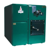
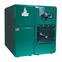
COMBINATION OPERATING INSTRUCTIONS
 Loading...