21
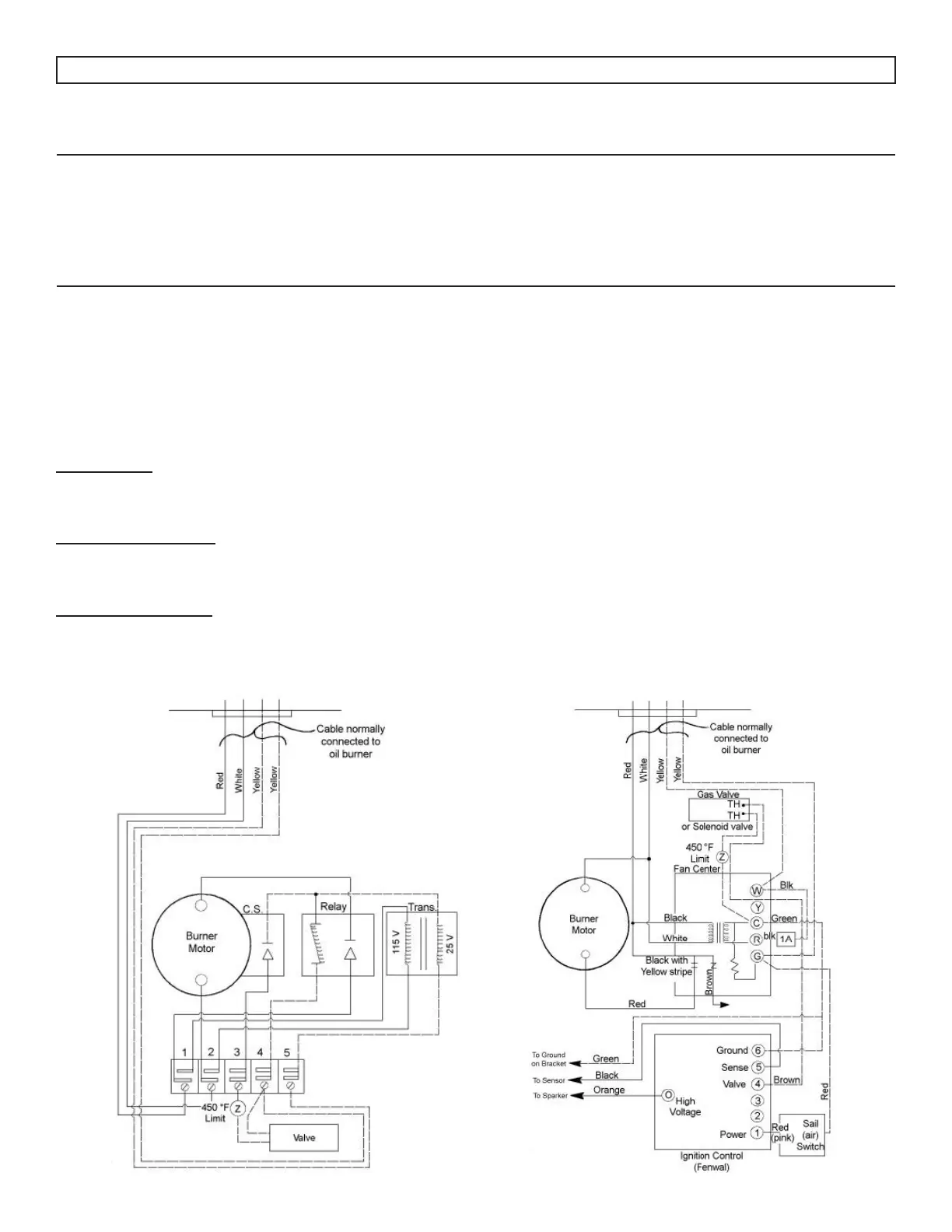
WIRING DIAGRAM FOR INSTALLATION OF
ADAMS GAS BURNER
WIRING DIAGRAM FOR INSTALLATION OF
AERO GAS BURNER
BURNER SPECIFICATIONS FOR NEWMAC FURNACES ***
Furnace
Model No.
B.T.U.H.
Output
Aero Oil
Burner
Model
No.
Nozzle Oil -
gph
Input Oil
B.T.U.H.
Aero Gas*
Burner
Model
No.
Gas Orice
Input
Gas
B.T.U.H.
Adams**
Gas Burner
Model No.
Gas Orice
L.P. Nat. L.P. Nat.
CL 86C-86G 86,000 F-AFC-2-8 .75 (80°)R 105,000 PGB-220 #23 #7 105,000 HP 225B-PS #33 ADJ.
CL 96C-96G 96,000 F-AFC-2-8 .85 (80°)R 119,000 PGB-220 #20 7/32” 120,000 HP 225B-PS 1/8” ADJ.
CL 115C-115G 111,000 F-AFC-3-8 1.00 (80°)R 140,000 PGB-220 #15 15/64” 145,000 HP 225B-PS #29 ADJ.
CL 140C-140G 140,000 F-AFC-3-8 1.25 (80°)R 175,000 PGB-220 #7 1/4” 170,000 HP 225B-PS #25 ADJ.
CL 155C-155G 152,000 F-AFC-3-8 1.35 (80°)R 189,000 PGB-220 #5 17/64” 185,000 HP 225B-PS #24 ADJ.
CL 170C-170G 169,000 F-AFC-3-8 1.50 (80°)R 210,000 PGB-220 #2 9/32” 200,000 HP 2258-PS 5/32” ADJ.
* Aero Gas Burner Model #PGB-220 must operate at 3.0" W.C. for natural gas and 3.5" W.C. for propane gas.
** Adams Gas Burner Model #HP 2258-PS must operate at 3.5" W.C. for natural gas and 11.0" W.C. for propane
gas. LP burners are designated by "LP". Example HP 2258-LP-PS.
*** Newmac furnaces are not certied in Canada with gas burners installed. Check with local authorities and
obtain their approval before installing a power gas burner. Refer to gas burner manual for proper installation and
service.
GAS BURNER INSTALLATION
GAS PIPING
All piping must comply with local codes and ordinances. Refer to the gas burner manual for further
recommendations.
BURNER MOUNTING
Install burner on the burner mounting plate with blast tube ush with the outside wall of the combustion chamber.
Connect the gas line to the burner by means of a union.
WIRING OF BURNER
Connect wiring according to Fig. 17-1A for the Adams burner and Fig. 17-1B for the Aero burner.
Figure 17-1A Figure 17-1B