7
5.0 CONTROLLER INTERCONNECTIONS
5.1 INTERCONNECTION WITH A PARALLEL BCD PRINTER
If printing the decimal point is not required or if the printer recognizes a positive
true binary address for the decimal point, simply connect the 24 line BCD outputs
(6 digits x 4) to the corresponding inputs of the printer. For negative true BCD and
decimal point address, install S4-B. If the parallel BCD printer accepts more than
6Êdigits, tie the unused inputs (digits 7, 8, etc.) to GND or high level, as required,
to print a BLANK on those positions.
Some printers or data acquisition systems can only accept a binary address of a
left-hand decimal point (001 corresponds to XXXXX.X instead of XXXXXX.). For
interconnection to such a system, connect each digit (4 BCD lines) to the next
more significant digit input of the printer (e.g., D1→D2, D3→D4, . . . D6→D7).
With this method, all of the digits are printed one position to the left;
therefore, the decimal point prints in the correct position. Digit 1 input and
other unused inputs of the printer should be tied to the appropriate level
to print a BLANK or zero.
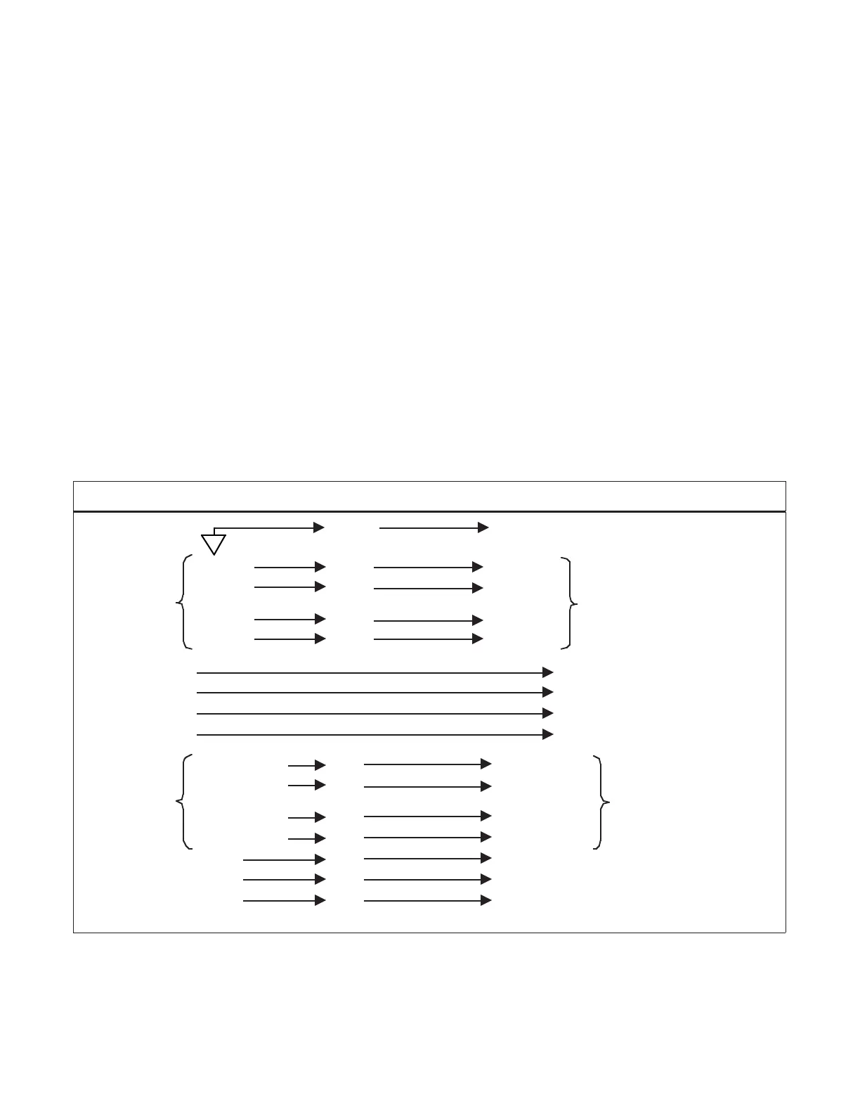
P6000A/P5000 Parallel BCD Parallel BCD Printer
ISO GND L7 GND
BCD 1 L18 BCD 1
DIGIT 1
BCD 2 U18 BCD 2
DIGIT 1
BCD 4 L17 BCD 4
BCD 8 U17 BCD 8
DIGIT 2 DIGIT 2
DIGIT 3 DIGIT 3
DIGIT 4 DIGIT 4
DIGIT 5 DIGIT 5
BCD 100 k L5 BCD 100 k
DIGIT 6
BCD 200 k U5 BCD 200 k
DIGIT 6
BCD 400 k L5 BCD 400 k
BCD 800 k U5 BCD 800 k
d.p. 1 U19 d.p. B1 Decimal point
d.p. 2 L12 d.p. B2 binary address
d.p. 4 U12 d.p. B4 (right-hand
decimal point)
Figure 5-1 Connections with a Parallel BCD Printer
Using Right-hand Decimal Point
1