20
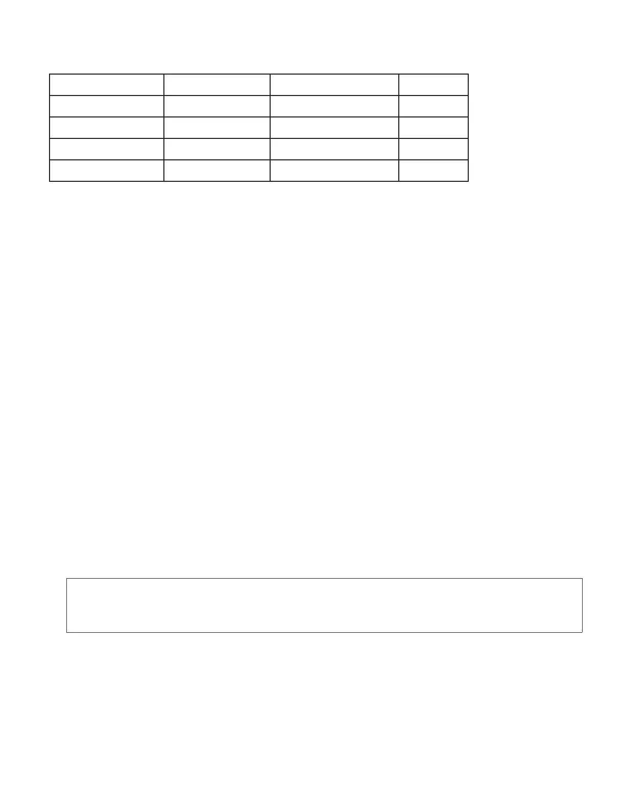
OFFSET RANGE VOLTAGE CURRENT
S1
*Z01 0.0 - 2.5 V 0.0 - 4.4mA
AB
Z02 2.5 - 5.0 V 4.4 - 8.8mA
AC
Z03 5.0 - 7.5 V 8.8 - 13.2mA
BD
Z04 7.5 - 10.0 V 13.2 - 17.7mA
CD
* Default Setting
Table 4-4 Offset Ranges
5.0 MECHANICAL INSTALLATION
The analog output board is positioned as an upper board in the P6000A/P5000.
Refer to the exploded view in the main board manual.
To install:
1. Hold the board upside-down with components facing the main board.
2. Position the P5 pins to mate with the J5 connector on the power supply
board.
3. Push the board downward until it rests on the upper rear panel and display
board.
6.0 FRONT PANEL SETUP
NOTE: The software switch SS3 of Configuration 2 must be set (XXX1XX) to
activate the analog output board. For more information, refer to
Section 4.1 of the P6000A/P5000 main board manual.