12
DUAL 8 A RELAY OPTION
1.0 GENERAL INFORMATION
The relay option provides two Form-C relays corresponding with LO and HI
setpoints of the P6000A/P5000. The inputs are internally connected and the
outputs are available on TB4, a 6-position barrier. TB4J, a mating screw-
clamp connector, is standard.
2.0 MECHANICAL INSTALLATION
The relay board is positioned as an upper board in the P6000A/P5000. Refer
to the exploded view in the main board manual.
To avoid electrical shock be sure to disconnect the unit from its power supply.
To install:
1. Hold the relay board upside-down with components facing the main
board.
2. Position the P5 pins to mate with the J5 connector on the power supply
board.
3. Push the board downward until it rests on the upper rear panel and the
display board.
3.0 ELECTRICAL CONNECTIONS AND JUMPER SELECTION
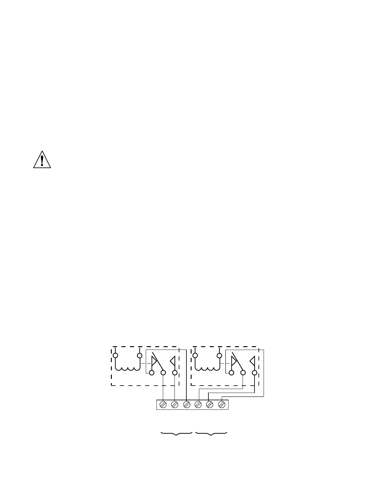
3.1 RELAY OUTPUTS
These outputs are available on the TB4 connector (Figure 3-1). The relay
board is rated for 8 A current with resistive and 3 A with inductive loads.
Push-on jumpers must be removed from pin groups S1 and S2 (Figure 3-2)
when the P6000A/P5000 is powered by an external battery (connected to
V+ of P2) with a voltage higher than 9 volts.
123 45 6
COMMON
NORMALLY
OPEN
NORMALLY
CLOSED
COMMON
NORMALLY
OPEN
NORMALLY
CLOSED
HIGH ALARM LOW ALARM
Figure 3-1 TB4 Connector with Electrical Connections