3
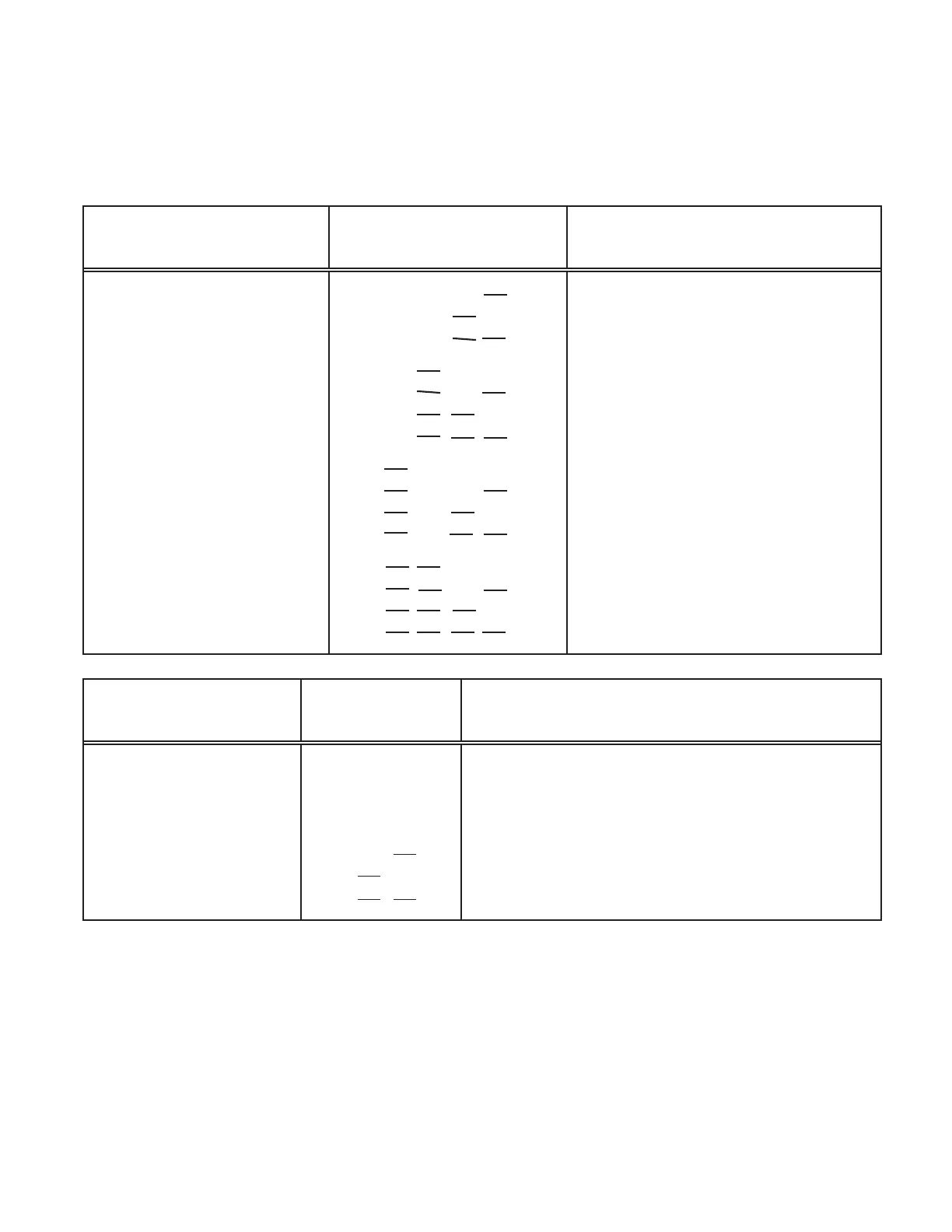
To enable the outputs, install jumpers on the pin groups and apply the proper address
on the instrument select lines as indicated below:
6-Digit
Parallel BCD
S1 Positions
Connector P4 with
Instrument Select Lines
U23 L23 U24 L24
Install jumpers on B8, B4, B2, B1* 0000
S2-A and S3-A; U5A
B8, B4, B2, B1 0001
and U6A on XU5A
B8, B4, B2, B1 0010
and XU6A sockets.
B8, B4, B2, B1 0011
B8, B4, B2, B1 0100
B8, B4, B2, B1 0101
B8, B4, B2, B1 0110
B8, B4, B2, B1 0111
B8, B4, B2, B1 1000
B8, B4, B2, B1 1001
B8, B4, B2, B1 1010
B8, B4, B2, B1 1011
B8, B4, B2, B1 1100
B8, B4, B2, B1 1101
B8, B4, B2, B1 1110
B8, B4, B2, B1 1111
Addressable 3-Digit
Parallel BCD
S1 Positions
Connector P4 with
Instrument Select Lines
U23 L23 U24 L24
ENABLES ENABLES
BCD 1 - 800 BCD 1k - 800k
OVRFLW, HI,LO,GO D.P. 1,2,4, POL
Install a jumper on
S2-B and S3-B. X, X, B2, B1 X, X, X, 0 X, X, 0, 1
U5A and U6A on X, X, B2, B1 X, X, X, 1 X, X, 0, 0
XU5B and XU6B X, X, B2, B1 X, X, X, 0 X, X, 1, 1
sockets. X, X, B2, B1 X, X, X, 1 X, X, 1, 0
0 = Open or TTL High level (more than 2.0 V) X = Don't Care
1 = Ground or TTL Low level (less than .8 V) * = Default Setting
Table 3-1 Required Address to Enable Outputs