December 2019 103 LDC-3706 Series Laser Controller
Laser Voltage Measurement Calibration
The following procedure calibrates the Laser voltage measurement. It only needs to be done
once: the range and modulation selections are not important to the voltage calibration.
1. Calibrate the laser current as described in the section above.
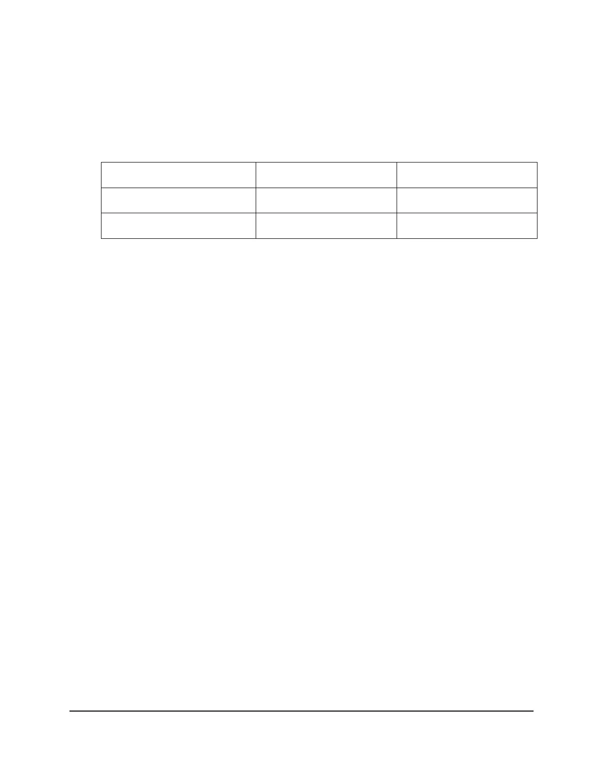
2. Connect a resistor across the laser output terminals, using the below chart to determine
which resistor to use for which unit:
LDC-3726 4.5 , 100W 9 Pin Connector
Pins 4,5 to 8,9
LDC-3736 4.5 , 100W 9 Pin Connector
Pins 4,5 to 8,9
LDC-37620 0.1 , 100W 9W4 Pin Connector
3, A4, 5 to
1, A2, 3
3. Connect a calibrated DMM across the load resistor. Navigate to the “LDV” selection in
the Laser Calibration submenu of laser parameter menu tree.
4. Enter the calibration mode by pressing the SET button while the “LDV” selection is
shown on the display. Then, press the LAS button to start the calibration process.
5. Measure the voltage using the DMM. Adjust the voltage shown on the lower display to
the match the measured voltage by turning the ADJUST knob. Then press the LAS
button.
6. The instrument will apply a second current after a short time. Repeat step 5 for the
second current.
7. Once the self-calibration is completed and calibration mode is exited, the calibration
constants will be stored to the non-volatile memory and the display will return to its
previous state.

 Loading...


