December 2019 14 LDC-3706 Series Laser Controller
Connections
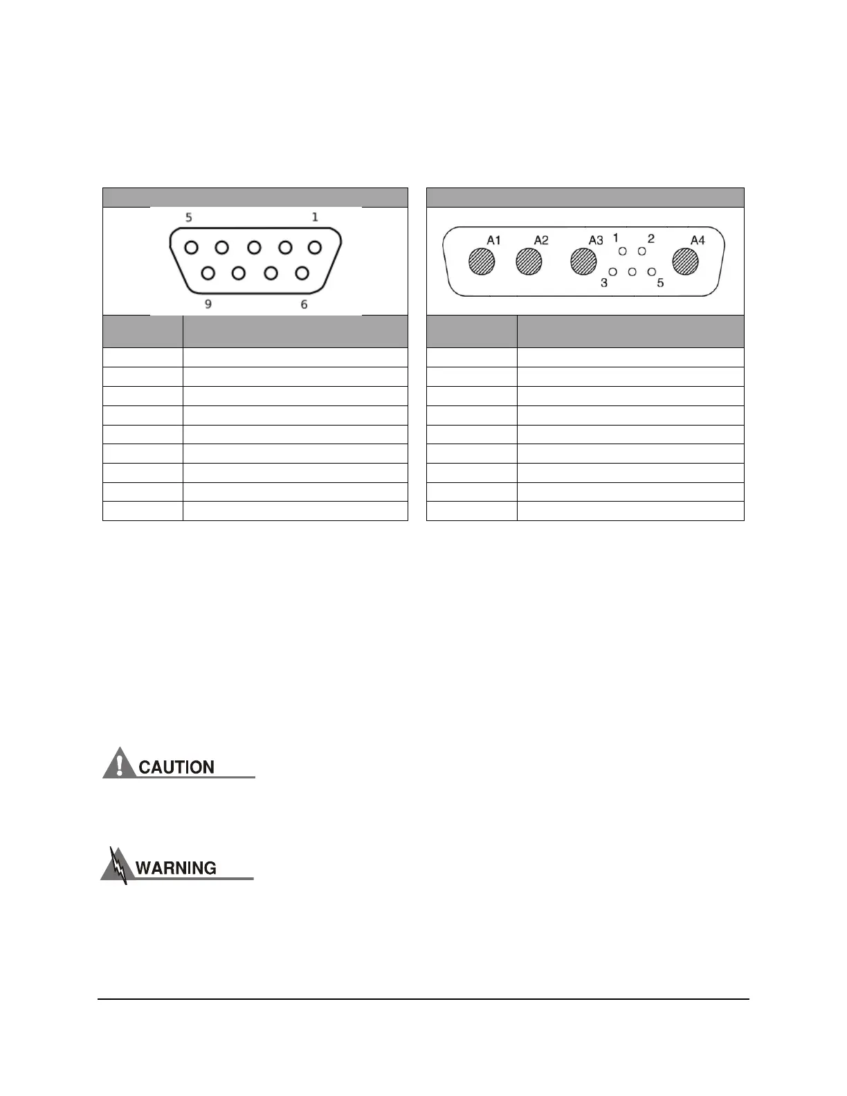
Current Source Output: A 9-pin D-sub connector is located on the rear panel of the LDC-3726 and
LDC-3736. A 9W4 connecter is located on the rear panel of the LDC-37620. The connections for
these connectors are shown below.
LDC-3726 & LDC-3736
LDC-37620
PIN
NUMBER
CONNECTION
PIN
NUMBER
CONNECTION
1 Interlock
A1 Laser Anode (+)
2 Interlock
A2 Laser Anode (+)
3 Chassis Ground
A3 Laser Cathode (-)
4 Laser Cathode Voltage Sense (-)
A4 Laser Cathode (-)
5 Laser Cathode (-)
1 Photodiode Anode (+)
6 Photodiode Cathode (+)
2 Photodiode Cathode (-)
7 Photodiode Anode (-)
3 Laser Anode Voltage Sense (+)
8 Laser Anode Voltage Sense (+)
4 Chassis Ground
9 Laser Anode (+)
5 Laser Cathode Voltage Sense (-)
Interlock Connections: For the LDC-3726 and LDC-3736, a short must exist between the Interlock
pins (pins 1 and 2) of the current source output connector in order for the laser output to be enabled.
The short can be a direct short across the pins or a switch to prevent laser operation until the switch
is closed. If a short does not exist between these two pins, the INTERLOCK LED illuminates on the
front panel and the laser output is disabled.
For the LDC-37620, a short must exist on the rear BNC interlock connector in order for the laser
diode output to be enabled. The short can be made using the 50 BNC terminator included in the
shipping kit or can be a switch to prevent laser operation until the switch is closed. If a short does not
exist between these two pins, the INTERLOCK LED illuminates on the front panel and the laser
output is disabled.
The interlock terminals on the LASER connector, pins 1 and 2, must be kept isolated
from all other connections including earth ground.
The Current Source output terminals of the LDC-3706 Laser Controller (Laser
Anode and Laser Cathode) should never be shorted together or loaded with less
than 0.1 Ω. Doing so may result in damage to the instrument.

 Loading...


