December 2019 15 LDC-3706 Series Laser Controller
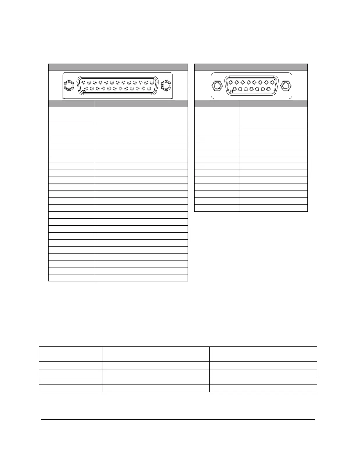
Temperature Control Output: A 15-pin D-sub connector is located on the back panel of the LDC-
3726. A 25-pin D-sub connector is located on the back panel of the LDC-3736 and LDC-37620. The
connections are shown below.
LDC-3736 & LDC-37620 LDC-3726
PIN NUMBER CONNECTION PIN NUMBER CONNECTION
1 Sensor
+
Sense Terminal 1 TE Module
+
2 Sensor
-
Sense Terminal 2 TE Module
+
3 Fan
+
3 TE Module
-
4
nalo
Ground 4 TE Module
-
5
nalo
Ground 5 TE Module Shield
6 Sensor / TE Module Shield 6 Temp. Sensor Shield
7 TE Module
+
Sense Terminal 7 Sensor
+
8 TE Module
-
Sense Terminal 8 Sensor
-
9 TE Module
+
9
nalo
Ground
10 TE Module
+
10 N/C
11 N/C 11 N/C
12 TE Module
-
12 N/C
13 TE Module
-
13 N/C
14 Sensor
-
14 Fan
+
*
15 Sensor
+
15 Fan
-
*
16 Fan
-
*Pins 14 and 15 are Fan (+) and Fan (-), respectively, for
only CC501S.
17 Cable ID 1
18 Cable ID 2
19 N/C
20 N/C
21 TE Module
+
22 TE Module
+
23 N/C
24 TE Module
-
25 TE Module
-
If you choose to assemble custom interconnect cables, 18AWG wire is recommended to minimize
voltage drop at high current. Note that the DB-25 connector pins are rated for I
nominal
= 2.5A, therefore
all four TEC+ pins (9, 10, 21, 22) must be used if 8 A is to be delivered to a load as well as all 4 TEC-
pins (12, 13, 24, 25) for the return.
Cable ID pin configurations will determine the maximum output current for the TEC and is only
applicable to products with the 25-pin D-sub connector.
MAX Output
Current Cable ID1 Cable ID2
Pin 17 (LDC-3736 & LDC-37620) Pin 18 (LDC-3736 & LDC-37620)
8
Pin 17 to
nalog Ground Pins 18 to
nalog Ground
5
Pin 17 to
nalog Ground Pin 18 N/C
1
Pin 17 N/C Pin 18 N/C

 Loading...


