2.1.2 Rear Panel
The rear panel connections are shown in Figure 2.2.
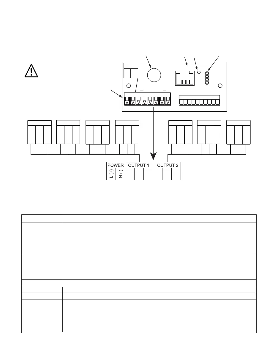
Figure 2.2 Rear Panel Power and Output Connections
Table 2.2 Rear Panel Connector
POWER AC/DC Power Connector: All models
OUTPUT 1 Based on one of the following models:
Relay SPDT
Solid State Relay (SSR)
Pulse
Analog Output (Voltage and Current)
OUTPUT 2 Based on one of the following models:
Relay SPDT
Solid State Relay (SSR)
Pulse
Network Communication Interface Section:
ETHERNET RJ45 interface for 10BASE-T connection.
RESET Button: Used for power reseting the Ethernet board.
ACTIVITY LED (Red) Blinking: Indicates network activities (receiving or
sending packets).
NET LINK LED (Green) Solid: Indicates good network link.
TX LED (Yellow) Blinking: Indicates transmitting data to the serial port.
RX LED (Green) Blinking: Indicates receiving data on the serial port.
ACTIVITY
NET LINK
TX
RX
81
ETHERNET
RST
RJ45 10BASE-T
CONNECTION
RESET
BUTTON
LED
INDICATORS
ANTENNA
LOCATION
POWER
L(+)
N(-)
16 OUTPUTS78
78
NOT USED
SSR RELAY PULSE SSR RELAY PULSEANALOG
8 7 6 5 4 3 2 1
OUTPUT 1OUTPUT 1OUTPUT 1OUTPUT 1 OUTPUT 2OUTPUT 2OUTPUT 2
POWER / OUTPUT
CONNECTOR
6 5 4 3 2 1 3 2 1 3 2 16 5 4 6 5 4 6 5 4
NO
NC
C
CUR
V
RTN
PUL
RTN
NO
C
NO
NC
C
PUL
RTN
NO
C
6
Use copper conductors
only for power connections

 Loading...


