71
PART 6
SPECIFICATIONS
ON/OFF CONTROL OUTPUT 1 & 2
Relay: 250 Vac or 30 Vdc @ 3 A (Resistive Load), SPDT
Solid State Relay (SSR): 20 to 265 Vac @ 0.05 to 0.5 A (Resistive Load);
continuous
DC Pulse: Non-Isolated; 10 Vdc @ 20 mA
Analog Output (Output 1 only) Non-Isolated, 0 to 10 Vdc or 0 to 20 mA, 500 Ω
max
Operation: Direct (cool), reverse (heat); deadband; single
sensing input
Configuration Output 1 and 2 can be configured as Alarm 1
and 2, respectively. Analog Output for Output 1
can be configured as retransmission.
ALARM 1 & 2 (PROGRAMMABLE)
Type: SPDT Relay, SSR, and DC Pulse
Operation: High/low, above/below, band, latch/unlatch,
normally open/normally closed and
process/deviation; front panel configurations;
single/multiple sensing input(s)
ANALOG RETRANSMISSION OUTPUT (PROGRAMMABLE)
Type: Non-Isolated, Retransmission 0 to 10 Vdc or
0 to 20 mA, 500 Ω max (Output 1 only).
Operation: Single sensing input; accuracy is +
1% of FS
when following conditions are satisfied:
1) Input is not scaled below 1% of Input FS.
2) Analog Output is not scaled below 3% of
Output FS.
INSULATION
Power to Output: 2300 Vac per 1 min. test
1500 Vac per 1 min. test
(Low Voltage/Power Option)
Power to Relays/SSR Outputs:
2300 Vac per 1 min. test
Relays/SSR to Relay/SSR Outputs: 2300 Vac per 1 min. test
GENERAL
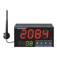
Display: 4-digit, 9-segment LED, 10.2mm (0.40
") and
21mm (0.83
") red, green and amber
programmable colors
Digital Filter: Programmable

 Loading...