1 Product description
Use latest device Documentation, Software and Firmware to ensure reliable operation of
the system (downloadable from www.nextys.com).
DCW20 is a microprocessor controlled unit that can perform 2 functions:
1. UPS rated 960W/20A usable in any system rated 12…48Vdc
2. DC/DC converter (non isolated) rated 960W/20A usable in any combination of IN/OUT
voltages 12…48Vdc
For the UPS function, it may use 1 battery of 12V, independently of the operating load voltage. For
any supply voltages (12…48Vdc) it may use also multiple battery configuration (10…58Vdc). DCW20
monitors the voltage coming from a DC power supply and in case of power failure a backup battery is
supplying the energy to the load. In normal condition the battery is kept charged by an integrated
battery charger supporting various battery chemistries.
As a DC/DC converter (no battery present) the input must be connected to the battery connector.
The input voltage is converted to any output voltage as per the set-up.
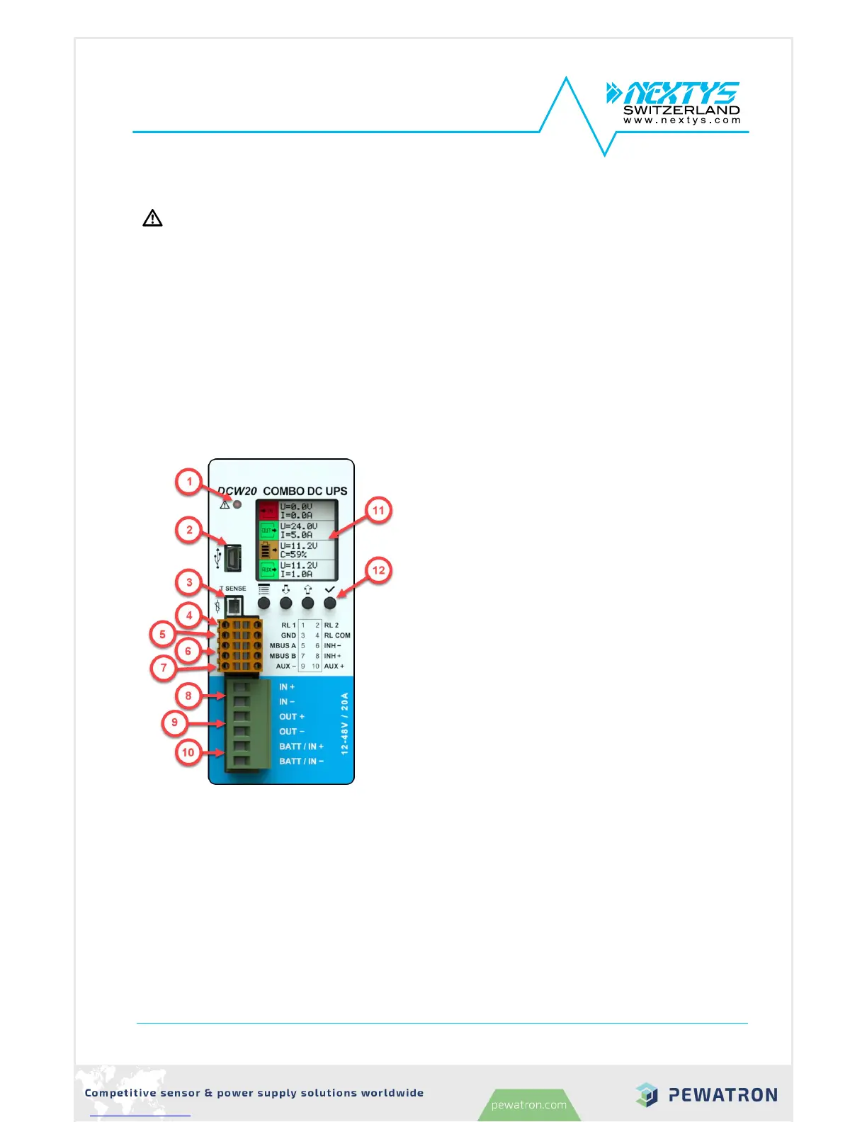
1. Alarm LED indicator: ON when the unit is in
backup. Blinks at 1Hz rate in case of error.
2. Modbus over USB: Used to connect a PC
running POWERMASTER or custom application
for remote monitoring and controlling. Firmware
update is also possible through USB
connection.
3. Temperature sensor: Optional temperature
sensor (P/N: WNTC-2MT) to measure the
battery temperature for protection and
temperature compensated charge method.
4. Relays dry contacts: 2 relays are present for
remote monitoring. See §4.2.26 for more
details.
5. Modbus over RS485: Used to connect a PC
running POWERMASTER or custom application
for remote monitoring and controlling. Firmware
update is also possible through RS485
connection.
6. Inhibit input: A voltage between 5VDC and
30VDC applied to this input activates the inhibit
function (§3.4).
7. Auxiliary output supply: Maximum 5A supply
from the battery (unregulated).
8. Input connection: 2 poles are provided for input connection. This must be connected to a
power supply rated 12…48VDC.
9. Output connection: 2 poles are provided for output connection. It must be connected to the
load to be backed up.
10. Battery connection: 2 poles are provided for battery connection. This must be connected to
the battery. Although the unit is protected, please respect the correct polarity.
11. Display area: provides information regarding the device status.
12. Control keys: 4 push buttons are provided to navigate through the menus and to select the
various functions.