3.1.1 Backup
The system is in backup mode if the supply for the output is sourced from the battery (input supply
missing). During backup the battery is monitored continuously to prevent over discharge.
A programmable backup timer (§4.2.24) is also implemented in order to fix a maximum backup time
during power outages. This allows preserving the battery life and shortening the recharge time,
avoiding discharging the battery when not needed.
During backup the internal Coulomb counter is used to give an estimation of the residual charge of
the battery.
Backup starts when the output voltage is lower than 90% of the “Nominal output voltage” (§4.2.20).
3.1.2 Battery health monitor
The battery health monitor is composed of:
Internal resistance measurement: The resistance is periodically measured. The internal
resistance is a good indicator of the battery health status; a sudden increase of the internal
resistance indicates a potential problem on the battery or on the battery wiring.
Temperature measurement: The battery temperature is monitored through an optional
temperature sensor (P/N: WNTC-2MT). The battery charger takes into account the battery
temperature and provides a temperature compensated charging voltage. In case of over or
under temperature the system disconnects the battery to prevent damage.
Coulomb counter: Estimates the remaining battery capacity and consequently the
available backup time.
Deep discharge protection: It protects against the deep discharge of the battery which
can lead to its irreversible damage.
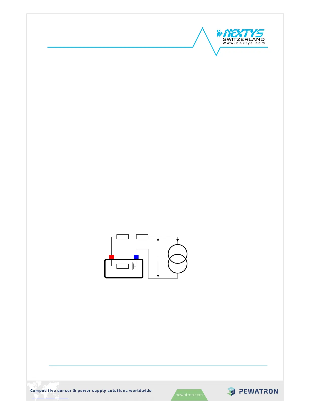
The battery internal resistance (Ri) is measured by draining a defined AC current through an active
load (AL) from the battery and measuring the AC voltage drop across the load terminals. The principle
is represented in Figure 4.
Figure 4: Internal resistance measurement
The measured resistance is the sum of the battery internal resistance, the cables resistance and the
connectors resistance, therefore cabling problem such as loose connectors are also detected with Ri
measurement.
When high capacity batteries and/or small and long cables are used R
cables
+R
con
may be > Ri.