8
with a point-to-point network.
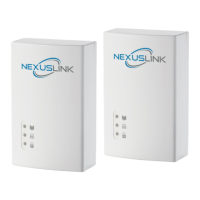
⚫ CASE 1: The COVERAGE LED in G.hn adapter 2 and G.hn adapter 3 will show the estimated level of the
PLC link receiving from G.hn adapter 1.
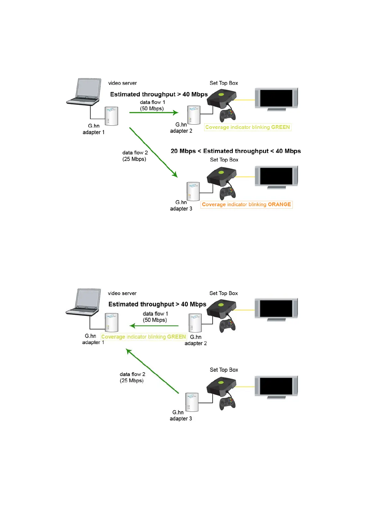
⚫ CASE 2: The COVERAGE LED in G.hn adapter 1 will show the estimated level of the PLC link from which
it is receiving the most amount of traffic at any given time. For example, if G.hn adapter 1 is receiving
traffic at 50Mbps from G.hn adapter 2 and is receiving 25Mbps from G.hn adapter 3, the COVERAGE LED
will show the level with reference to the G.hn adapter 2 link, as shown in the following figure.