20
Controls and Connectors
Controls
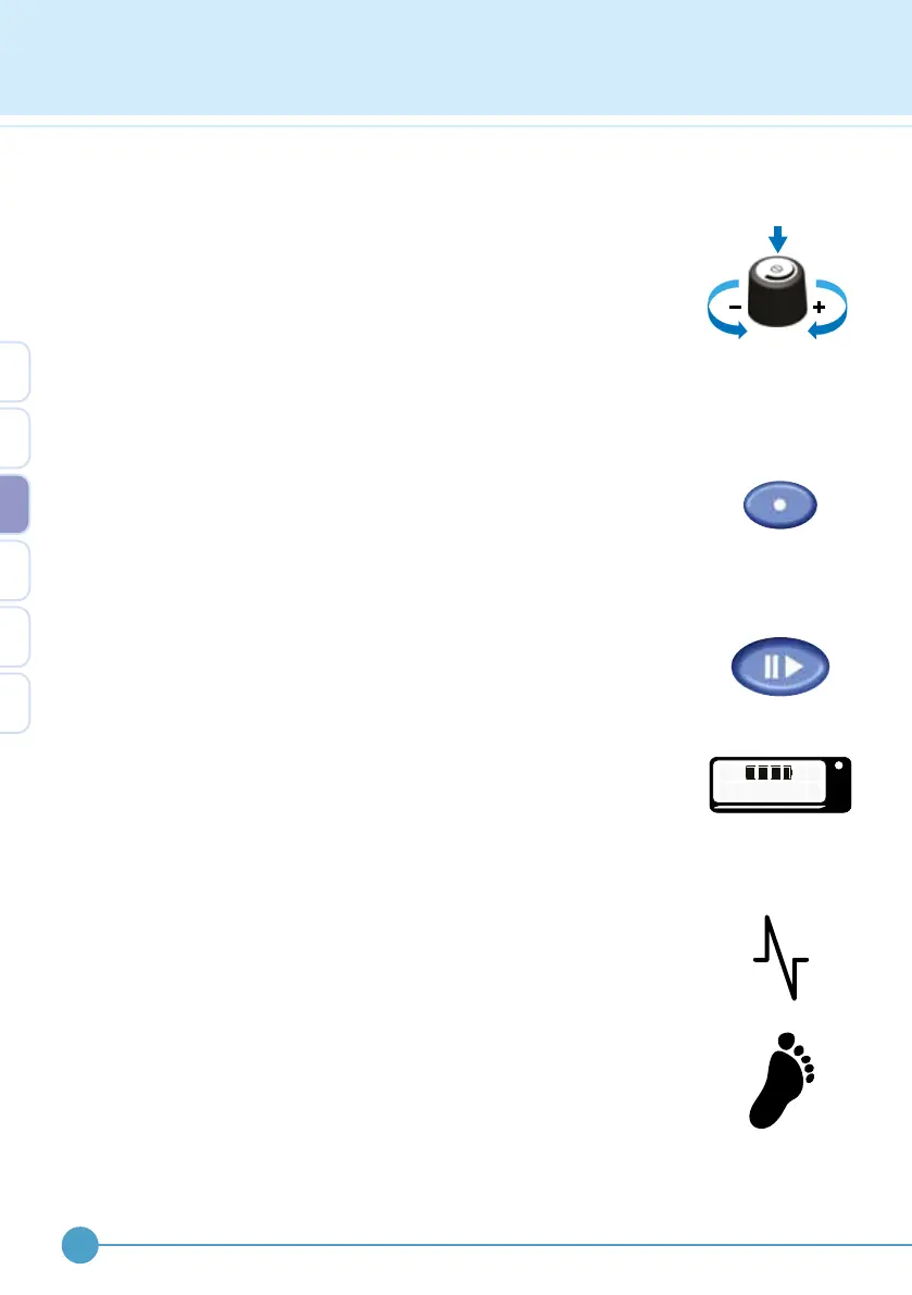
Control knob
This control has three actions;
• Twist clockwise to turn up or ‘increase’
• Twist anticlockwise to turn down or ‘decrease’
• Press down and release to unlock, click or select
The control knob is also used to navigate the menu and select menu
options.
Test button
This button is used to test the output level and to assist in nding the
correct electrode position. The test button only functions when the
stimulator is paused. A single envelope or “burst” of stimulation is given
for each press of the test button.
Pause button
This button starts (active mode) and stops (pause mode) stimulation.
Active and pause modes are cycled by pressing the pause button. In
walk mode, a long beep is given for entering active mode and a shorter,
higher pitched beep is given for exiting active mode.
When the pause mode is entered, the display will briey show the battery
condition. To keep the battery condition displayed for longer, continue to
hold down the pause button.
Connectors
Electrode lead socket
Located on the side of the case near the top and identied with a waveform
symbol. This is where the electrode lead is plugged into.
Footswitch lead socket
Located on the side of the case below the electrode socket and identied
with a footprint symbol. This is where the footswitch lead is plugged into.
The ODFS
®
Pace XL can use a wired footswitch. Simply plug in the
footswitch when the ODFS
®
Pace XL is paused. To revert to wireless,
disconnect the wired footswitch.
OML
GO OD
3
 Loading...