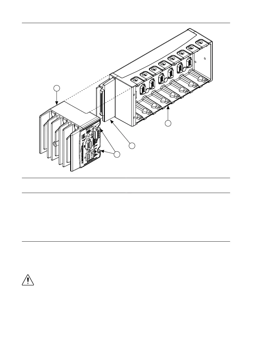
Figure 3. Installing the cRIO-9012/9014 in the Chassis
1. Controller
2. Captive Screws
3. Controller Slot
4. Reconfigurable Embedded Chassis
3. Slide the controller onto the controller slot on the chassis. Press firmly to ensure the
chassis connector and the controller connector are mated.
4. Using a number 2 Phillips screwdriver, tighten the two captive screws on the front of the
controller to 1.3 N · m (11.5 lb · in.) of torque.
Connecting the Controller to a Network
Connect the controller to an Ethernet network using the RJ-45 Ethernet port on the controller
front panel. Use a standard Category 5 (CAT-5) or better shielded, twisted-pair Ethernet cable
to connect the chassis to an Ethernet hub, or use an Ethernet crossover cable to connect the
chassis directly to a computer.
Caution To prevent data loss and to maintain the integrity of your Ethernet
installation, do not use a cable longer than 100 m. If you are using 100 Mbps
Ethernet, National Instruments recommends using a CAT-5 or better shielded
twisted-pair Ethernet cable.
If you need to build your own cable, refer to the Cabling section for more information about
Ethernet cable wiring connections.
The host computer communicates with the controller over a standard Ethernet connection. If
the host computer is on a network, you must configure the controller on the same subnet as the
NI cRIO-9012/9014 User Manual and Specifications | © National Instruments | 5