© National Instruments Corporation 5 SCC Quick Start Guide
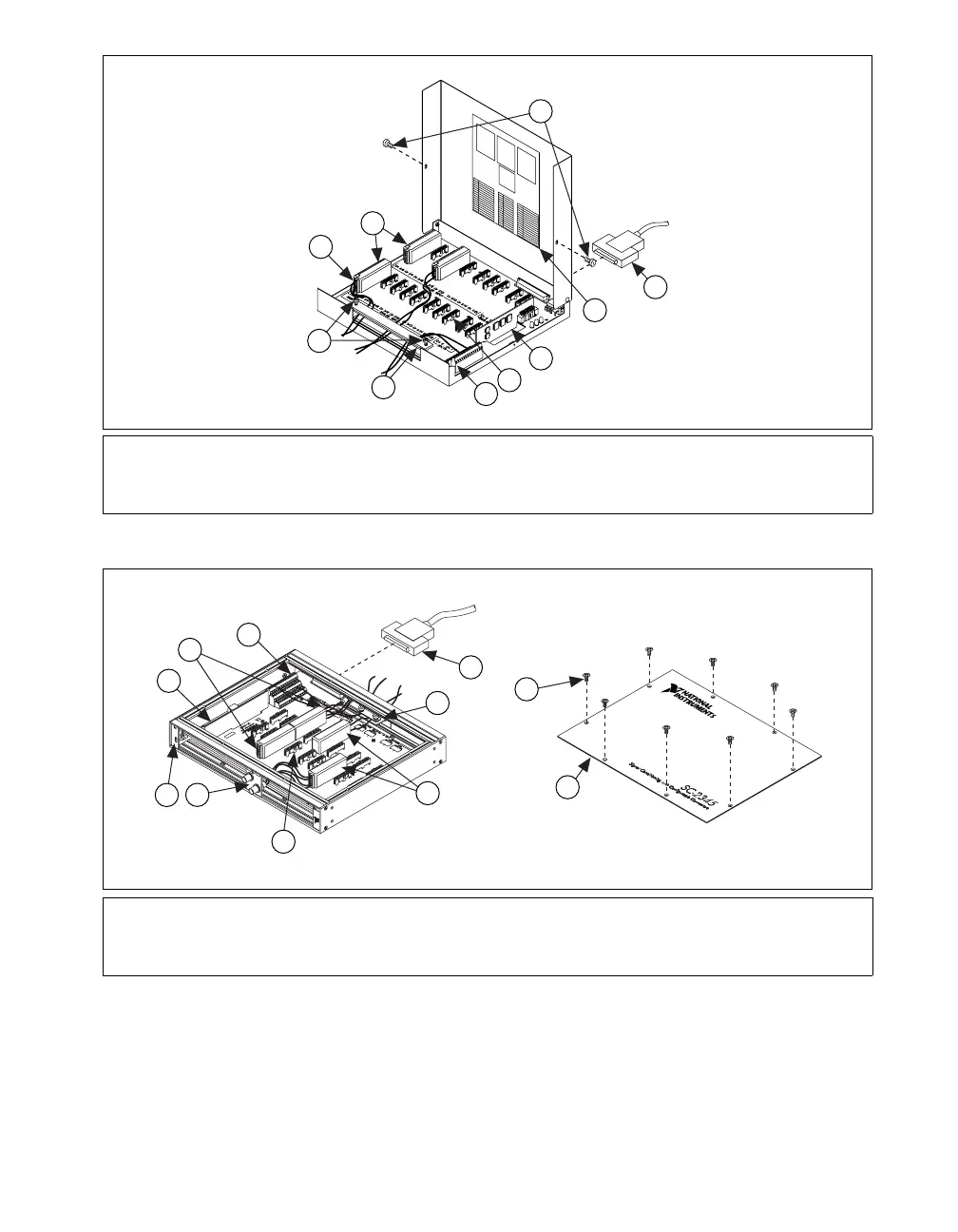
Figure 2. SC-2345 Carrier Installation Diagram
Figure 3. Installing a Rear Cabled SC-2345 with Configurable Connectors
1 Screw Terminals
2 SCC Modules
3 Cover Screws
4 68-Pin Shielded Cable
5 Quick Reference Label
6 SCC-PWR
XX
7 SCC Connector Block Socket
8 Screw Terminal Block
9 Top Strain-Relief Bar
10 Top Strain-Relief Screws
1 68-Pin Shielded Cable
2 Strain-Relief Panelette
3 SCC Modules
4 SCC Connector Block Socket
5 BNC Panelette
6 Power LEDs
7 SCC-PWR
XX
8 Screw Terminals
9 Screw Terminal Block
10 Top Cover
11 Cover Screws
6
8
P
o
s
it
io
n
E
S
e
r
i
es
P
in
N
u
m
b
e
rs
a
n
d
N
a
m
e
s
T
e
r
m
in
a
l
B
lo
c
k
D
e
f
in
i
ti
o
n
R
o
w
B
R
o
w
C
P
oss
ib
le SC
C C
on
fig
uratio
n
s
(
C
o
lo
r
in
d
ic
a
t
e
s
st
rip
e
o
n
S
C
C
)
R
ow
A
P
/
N
1
8
4
1
1
4
A
-0
1
R
eferen
ce
L
abe
l
S
C
-2
345 Q
u
ick
7
5
10
3
2
S
C
C
-
X
X
X
X
S
C
C
-
X
X
X
X
S
CC
-
X
X
X
X
8
6
4
1
9
C
H
1
C
H
2
4
3
2
1
9
8
7
11
10
6
S
C
C
-
X
X
X
X
S
C
C
-
X
X
X
X
S
C
C
-
X
X
X
X
S
C
C
-
X
X
X
X
5
 Loading...