SCC Quick Start Guide 6 ni.com
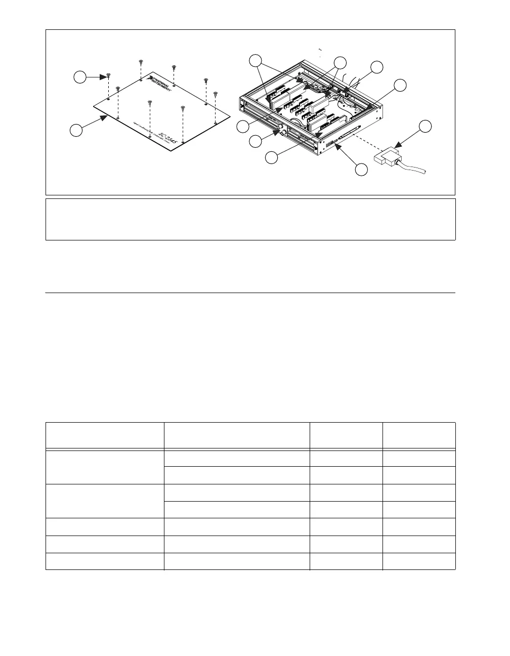
Figure 4. Installing a Side Cabled SC-2345 with Configurable Connectors
Step 4. Set Up the SC-2345/SC-2350 Carrier
The following section describes how to set up common to both the SC-2345
and the SC-2350 carriers.
Procedure 1: Install the Connectors and Panelettes
If you have selected an SC carrier with configurable connectors, install the
connector and interface panelettes. Some panelettes occupy more than
one panelette slot. Table 1 lists the panelette specifications.
1 Cover Screws
2 Top Cover
3 Screw Terminals
4 SCC Modules
5 Strain-Relief Panelette
6 Screw Terminal Block
7 68-Pin Shielded Cable
8 Power LEDs
9 SCC-PWR
XX
10 BNC Panelette
11 SCC Connector Block Socket
Table 1. Panelette Options
Panelette Description
Connectors/Units
per Panelette
Slot Width
Mini-thermocouple jack
J- or K-type 2 1
Uncompensated 2 1
Thermocouple jack
J- or K-type 1 1
Uncompensated 1 1
BNC BNC connector 2 1
SMB SMB connector 4 1
Banana jack Banana jack 2 1
C
H
1
C
H
2
6
7
2
10
9
8
3
4
5
11
SCC-
XXXX
SCC-
XXXX
SCC-
XXXX
SCC-
XXXX
1
 Loading...