SCC Quick Start Guide 4 ni.com
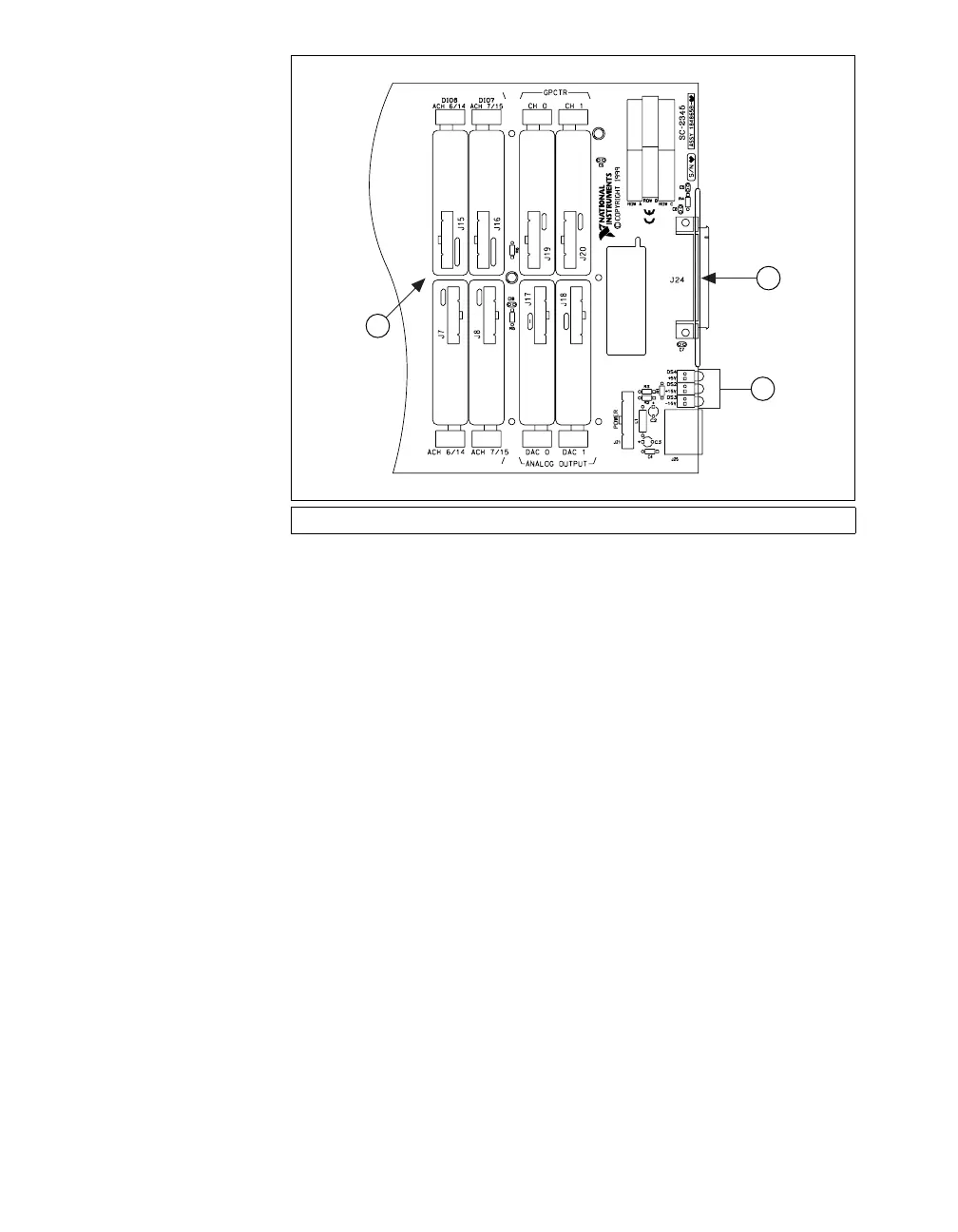
Figure 1. Connector J24 Location
The chassis ground terminal on the SC-2345/2350 carrier and the
electromagnetic interference (EMI) gasket attached to the strain relief of
the SC-2345 connector block are for grounding a floating source (1 mA
maximum). Do not use these terminals as safety earth grounds. For more
information about the SC-2345/2350 carrier, refer to the SC-2345/2350
Carrier User Manual.
Figure 2 shows the SC-2345 carrier with the signal wires connected.
Figures 3 and 4 show the two types of cabling on the SC-2345 with
configurable connectors.
1 Connector J24 2 Power LEDs 3 SC-2345 Carrier
2
1
Digital I/O
or 1st Stage
of a Dual Stage
AI Configuration
Digital I/O
or 1st Stage
of a Dual Stage
AI Configuration
General Purpose
Counter/Timer
Channel 0
General Purpose
Counter/Timer
Channel 1
Analog Output
DAC 1
Analog Output
DAC 0
Single Stage AI
or 2nd Stage
of a Dual Stage
AI Configuration
Single Stage AI
or 2nd Stage
of a Dual Stage
AI Configuration
3
 Loading...