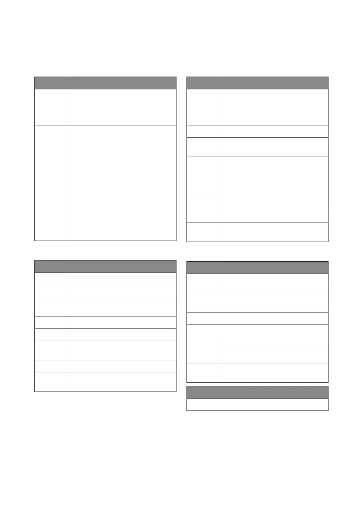
Soft-start card (QA30)
IndicationLED
A steady light indicates correct control
voltage 230 V+/- 15%.
A flashing light indicates that control
voltage is < 90 V.
Power:
Green
Shows alarm status.
2 flash: Low incoming voltage (<190 V for
1sec). Automatic reset with 5 minutes re-
covery.
3 flash: If an over current is detected under
the ramp. 2x automatic resets with 5
minutes recovery, requires that the control
voltage is broken for 1 minute.
4 flash: Indicates defective start condens-
er/relay.
5 flash: Unsuccessful voltage stepping. 2x
automatic resets with 5 minutes recovery,
requires that the control voltage is broken
for 1 minute.
Error: Red
MODBUS 40
IndicationLED
No function.BATT
No function.RUN
Flashes during communication with the
heat pump.
COM1
No function.LED 4 (-)
No function.LEV
No active communication between Mod-
bus 40 and "external control".
COM2
No function.SYNC
A steady light means that supply voltage
is OK.
VCC
SMS 40
IndicationLED
A steady light if voltage in the battery is
above 0 V.
Out if the battery is discharged or if no
battery is installed.
BATT
No function.RUN
Flashes during communication with heat
pump and at start-up.
COM1
A steady light that indicates that 12V is OK.LED 4 (-)
Steady light when the GSM signal is OK.
Out if the GSM signal is too low.
LEV
Flashes during communication with the
GSM modem.
COM2
Flashes when SMS 40 sends/receives SMS.SYNC
A steady light means that supply voltage
is OK.
VCC
Accessory card (AA5)
IndicationLED
A steady light means that 12V is OK.Power:
Green
Flashing once/sec. Indicates that the pro-
cessor is OK.
Run: Green
Flashes irregularly during communication.Com: Green
Continuous light during active output.PWM1: Or-
ange
Continuous light during active output.PWM2: Or-
ange
A steady light means that the relevant relay
is engaged.
K1 - K4: Or-
ange
FunctionOutput
See relevant accessory.
F1245Chapter 5 | Component description26
 Loading...


