11NIBE F1330
Installation / Adjustment
Pipe connections
Pipe connections
General
Pipe installation must be carried out in accordance with
current norms and directives. F1330 can work up to a
return temperature of approx. 58 °C and an outgoing
temperature from the heat pump of approx. 65 °C. When
F1330 is not equipped with shut off valves, these must
be fitted outside of the heat pump to assist future service
work.
Pipe connections (heating medium)
Pipes are connected at the rear of the heat pump. The
necessary safety equipment, shutoff valves (fitted as close
as possible to the heat pump), and the particle filter and
flexible hoses supplied must be fitted.
When connecting to a system with thermostats on all
radiators/coils, a relief valve must be fitted, or some of the
thermostats must be removed to ensure sufficient flow.
The unit is designed to allow hot water production with
one or two heat pump modules. However, this requires
different pipework and a different electrical installation.
Pipe connections (brine)
When dimensioning the collector, consideration must
be given to the geographical location, type of rock and
ground and the degree of coverage provided by the heat
pump.
When installing the collector hose, ensure it rises constant-
ly towards the heat pump to avoid air pockets. If this is not
possible, install high points to vent the air.
All brine pipes in heated rooms must be insulated against
condensation.
As the temperature of the collector system can fall below
0 °C it must be protected against freezing down to -15 °C.
One litre of ready mixed brine per meter of collector hose
(applies when using PEM-hose 40 x 2.4 PN 6.3) is used as
a guide value when making the volume calculation.
The collector system should to be labelled to show what
antifreeze has been used.
Shut-off valves should be installed as close to the heat
pump as possible. Fit a particle filter to the incoming pipe.
In the case of connection to an open groundwater system,
an intermediate frost-protected circuit must be provided,
because of the risk of dirt and freezing in the evaporator.
This requires an additional heat exchanger.
AV Shutoff valve
BK Rock collector
EXP Level vessel
JK Soil collector
KB-in Brine in
KB-ut Brine out
SF Particle filter
*The brine pump for 60 kW is supplied and installed externally out-
side the heat pump.
The pipe system needs to be flushed out
before the heat pump is connected so that
debris cannot damage component parts.
This applies to both hot and cold sides.
The heat pump’s pipe must not be
soldered directly, due to internal sensors.
Compression ring or press coupling should
be used.
NOTE!
NOTE!
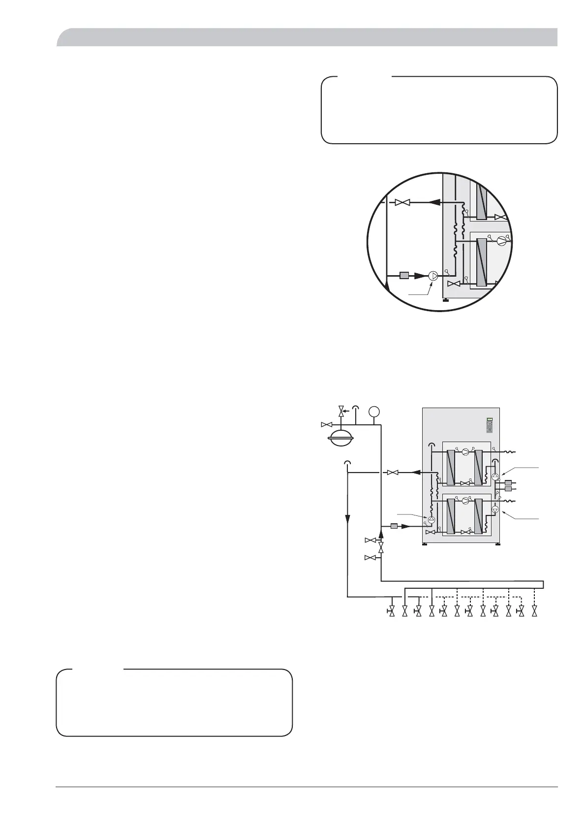
Connecting external brine pump (60 kW only)
The enclosed external brine pump for F1330 -60kW is
installed externally outside the heat pump on incoming
connection (4) (see image above).
B
A
BK / JK
KBP*
VBP-B
VVR
VVF
VBFB
VBRA/VBRB
KBut
KB-in
VBFA
AV
VBP-A
SF
EXP
P
A B I II
A B
13.43
1.0
P
50.0°C
Varmvattentemperatur