26 NIBE F1330
Installation / Adjustment
Description of functions - Basic functions
Electrical additional heater
The electrical additional heater can be controlled by up
to 6 relays, of which 3 are on the Base card and 3 on
Expansion card 11.
F1330 delivers 230 V control signals for additional heat,
i. e. signals to control external relays, contactors etcetera,
however, not to power these.
In standby mode, the output ETS-3/OP (Base card) and the
output ETS-6 (Expansion card 11) are voltage fed.
Stepping takes place at intervals of at least 3 minutes be-
tween the steps when stepping up. When stepping down
the interval between steps is at least 1 minute.
When HPAC is connected on the Base card and selected
in menu 9.1.10, the outputs ETS-1 and ETS-2 are used to
control this and accordingly can not be used to control the
electrical additional heater. With that, the first electrical
step is shifted to ETS-3.
When the oil boiler is connected and Electri/Oil is selected
in menu 9.1.8, the relay ETS-3 is used to control the oil
boiler and the electrical additional heater then jumps over
this relay when stepping.
All electrical output can be force out by shorting the input
Tariff B (TB).
By using the Fuse knob (100) (adjustable to 16, 20, 25, 35,
50 or 63 A) the current through the ring cores can be lim-
ited. The last connected electrical output is automatically
disconnected if this happens. Extra hot water - immersion
heater (XVV) is disconnected last of all. The setting can be
checked in the menu 8.3.1.
The Max electrical output knob (101) permits a limitation
in the number of available electrical steps as part of the
number of possible electrical steps according to immersion
heater type (menu 6.2.1) and relay setting (menu 6.2.2).
Variable setting between 10 and 100 percent. The setting
can be checked in the menu 8.3.2.
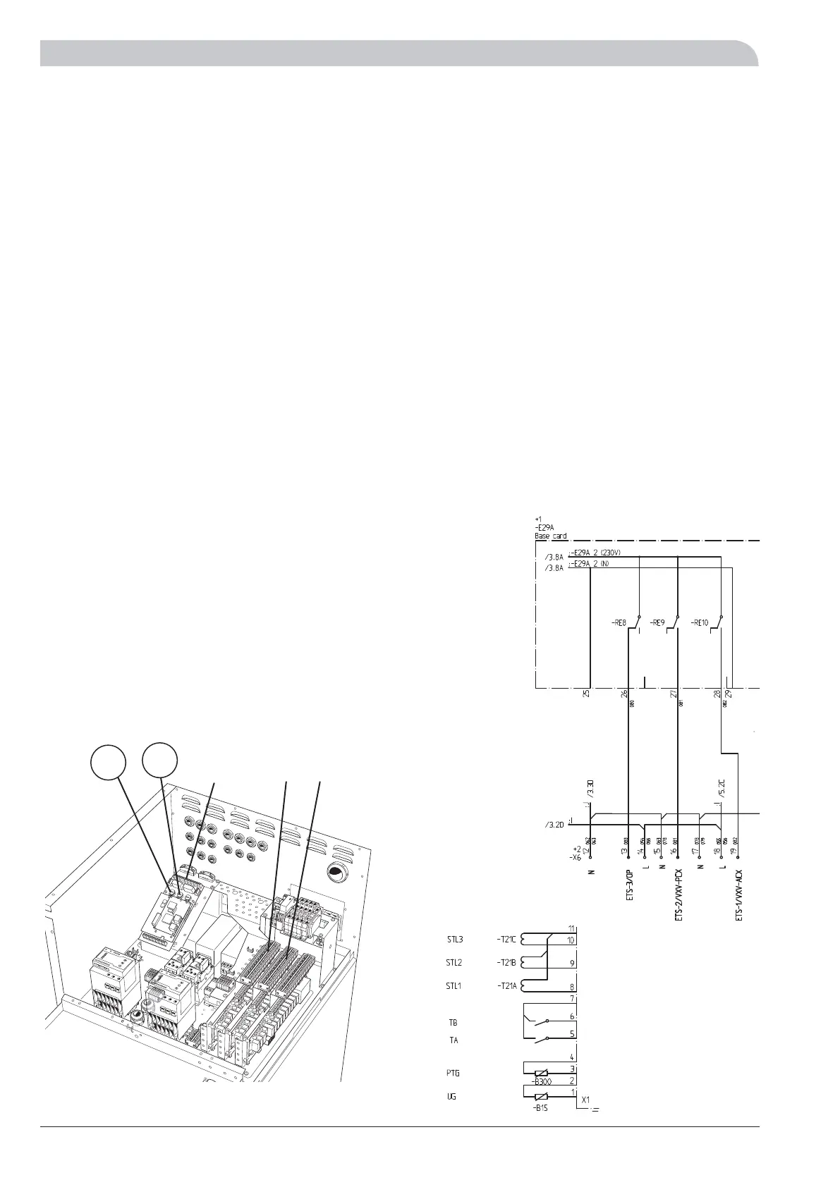
Connection of electrical additional heater
ETS-1 is connected to terminal blocks X6:17 (N) and X6:19
(230 V with activation).
ETS-2 is connected to terminal blocks X6:15 (N) and X6:16
(230 V with activation).
ETS-3 is connected to terminal blocks X6:12 (N) and X6:13
(230 V with activation).
ETS-4, ETS-5 and ETS-6 are accessories (Expansion card 11)
ETS-4 is connected to terminal blocks X6A:15 (N) and
X6A:14 (230 V with activation).
ETS-5 is connected to terminal blocks X6A:11 (N) and
X6A:13 (230 V with activation).
ETS-6 is connected to terminal blocks X6A:11 (N) and
X6A:12 (230 V with activation).
Current transformers (STL1, STL2 and STL3) are connected
to the terminal blocks X1:8-X1:11 on the EBV-card. X1:11
is the common conductor for the three current transform-
ers. The current transformers are installed in the distribu-
tion box in the house using unscreened LiYY or screened
LiYCY cable. The cable cross section should be a minimum
of 2 x 0.25 with cable lengths up to 50 m.
LEK
+EBV-card
101
100
X6 X6aX1
The heat pump in the picture is fitted with accessories.