36 NIBE F1330
Installation / Adjustment
Description of functions - Expansion card 11
Pool
A shuttle valve (VXV-P) can be connected to control one
part of, or the entire, heating medium flow to a pool
exchanger. The shuttle valve, or, if required - the shut-
tle valves (however, with the same control signal), is/are
installed on the heating medium circuit that goes to the
radiator system as normal. The compressor modules that
are connected via pool exchange valve must be selected
as available for pool operation in menu 5.4.12 and 5.4.13.
Circulation pump VBP3 must be installed for pool opera-
tion.
During pool heating, the heating medium circulates be-
tween the heat pump and pool exchanger using the heat
pump’s internal circulation pumps (VBP-A respectively
VBP-B). VBP3 circulates the heating medium around the
heating system and additional heat can be connected as
required at the same time as the flow line sensor (FG) con-
tinuously senses the heating requirement of the house.
Start and stop temperatures for pool heating are set in
menu 6.5.1 respectively 6.5.2. Heating operation is nor-
mally prioritised before pool heating, but shifting between
pool heating and heating operation can be set in menus
6.5.3 and 6.5.4 if required. If the same value is set in both
the menus, heating operation is prioritised before pool
heating.
If several compressors are available for pool operation,
these start at 5 minute intervals until no more are available
or the number of started compressors is the same as the
number that is selected in menu 6.5.5.
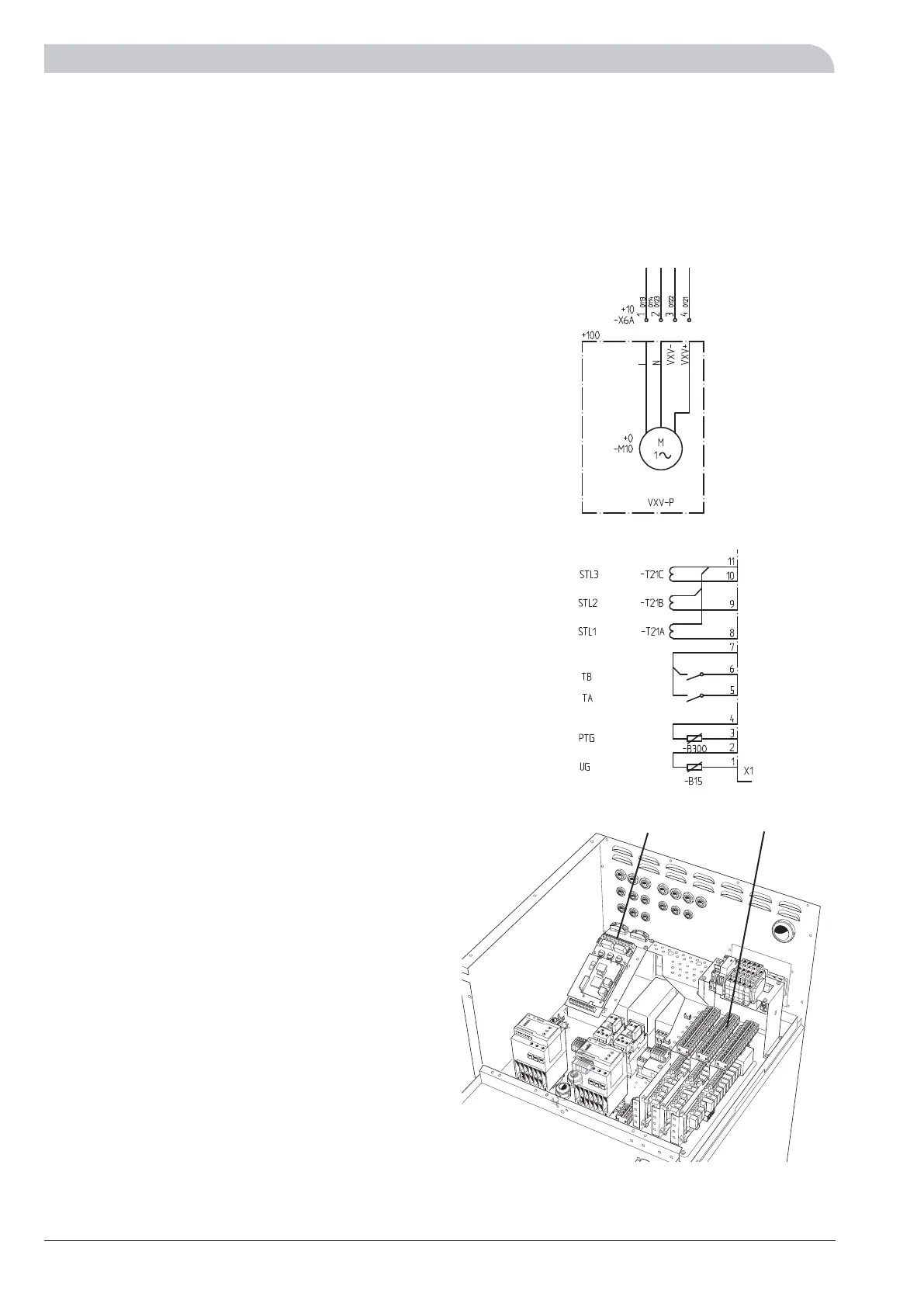
Connection of pool
Shuttle valves (VXV-P) is connected to the terminal blocks
X6A:1 (230 V), X6A:2 (N) and X6A:3 (NC) or X6A:4 (NO).
The pool temperature sensor (PTG) is either fitted on the
circulation pipe for the pool water (presupposes continuous
circulation) or in a submerged tube in the pool. The sen-
sor is connected to screw terminals X1:3 and X1:4 on the
EBV-card.
The heat pump in the picture is fitted with accessories.
LEK
+EBV-card
X6AX1