23NIBE F1330
Installation / Adjustment
Description of functions - Basic functions
The outline diagram with docking instructions is
available at www.nibe.eu
Quick guide - menu settings
heat production
Operating mode
The menu is accessible via the operating mode
button. Whether heat production is permitted
is selected here and if so whether the electrical
additional heater may be used.
Menu 2.1 Curve slope [N]
The selected curve slope for the heating curve is shown
here. The value is adjustable between curve 1 and 15,
or in Own curve. The values for own curve are set in
menu 2.6.0. The factory setting is 9.
Menu 2.2 Offset heating curve [N]
The chosen offset for the heating curve is shown here.
The value is adjustable between -10 and +10. NOTE!
The value cannot be changed using the plus and minus
buttons, only by using the Offset heating curve knob on
the Master unit.
If the RCU is connected, the set offset is shown via RCU
between brackets. The actual offset then becomes the
total of the set offset and RCU offset.
Menu 2.3 Min. flow temp. [U]
The set minimum level for the flow temperature to the
heating system is shown here. The calculated supply
temperature never drops below this level irrespective of
the outdoor temperature, curve slope or offset heating
curve. The value is adjustable between 2 and 65 °C.
The factory setting is 15 °C.
Menu 2.4 Max. flow temp. [U]
The set maximum level for the supply temperature to
the heating system is shown here. The calculated sup-
ply temperature never exceeds this level irrespective of
the outdoor temperature, curve slope or offset heating
curve. The value is adjustable between 10 and 80 °C.
The factory setting is 55 °C.
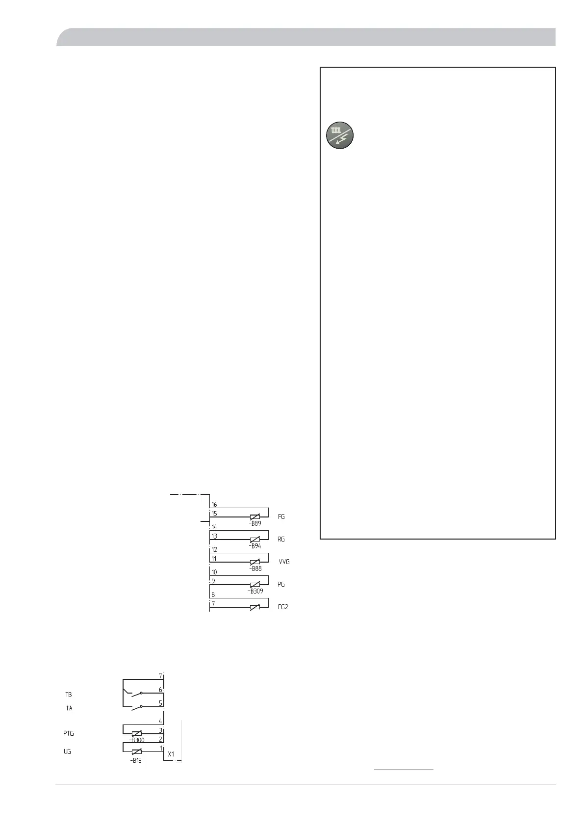
Connection of heat production
The flow temperature sensor (FG) is installed on the flow
line towards the heating system. For a more exact place-
ment see each docking option. The sensor must make
good contact with the measurement area to give the best
function. When a submerged tube is not available, use the
supplied copper tube. The sensor is connected to screw
terminals X4:15 and X4:16 on the EBV-card.
The return line temperature sensor (RG) is installed on
the return line from the heating system. For a more ex-
act placement see the selected docking option. The sen-
sor must make good contact with the measurement area
to give the best function. When a submerged tube is not
available, use the supplied copper tube. The sensor is con-
nected to screw terminals X4:13 and X4:14 on the EBV-
card.
The outside sensor (UG) must be installed in a shaded loca-
tion on a wall facing north or north-west, where it will not
be affected by any morning sun. The sensor is connected
using a two-core cable to the terminal blocks X1:1 and
X1:2 on the EBV-card.
The external heating medium pump (VBP3) control signal
is connected to terminal block X6:1 (230 V), X6:2 (N) (max
0.2 A) on the relay card.
Note that F1330 delivers 230 V control signals intend-
ed to control external contactors and not to drive
pumps.
+EBV-card
X4
+EBV-card